BidRidge › Designers › Guide › Chapter 34

Chapter 34 · Roofing & Siding DesignerBeta

Sample Office Building, 3 stories: 15,579 sf of metal, ACM, fiber cement and thin brick cladding; and a standing seam warehouse roof

From the designer's commercial samples: a 120 x 60 ft, 3-story Type IIB office with concealed-fastener metal panels, ACM at the entry, fiber cement panels on the east wall and a thin brick base, over mineral wool on clips and girts or polyiso under hat channels. The NFPA 285 flags with their IBC sections, the panel layout and order list, attachment by wind zone, the sealant joint schedule, trims and access; then a warehouse roof in structural standing seam over purlins with an office wing in architectural standing seam, its roof wind zones, clips, snow retention and flashings; and the Submittal sets.

In the Roofing & Siding Designer, tap Open project and pick the sample file: it opens as the office building's walls in this chapter. The metal roofs are the designer's Sample Warehouse, standing seam roof (New design).

Narrated walkthrough, 2:04. Captions on.

The sample in numbers

  • Cladding
    15,579 sf
    4 systems · 36 panel marks · 4 walls
  • NFPA 285
    3 tested
    Type IIB, 46.8 ft: WRB, foam plastic and MCM, each marked as a tested assembly
  • Wind zones
    a = 6'
    walls: zone 5 corners, zone 4 field
  • Sealant
    1,710.3 LF
    8 joint types with backer rod
  • Metal roof
    11,739.7 sf
    325 panels · 2,539 clips · 12 snow rows
  • Sheets
    15
    walls Submittal set, ARCH D (roof: 12 on ARCH D, 14 on 11x17)

Step by step

Step 1: Open the commercial cladding sample in the Roofing & Siding Designer

Step 1: Open the commercial cladding sample

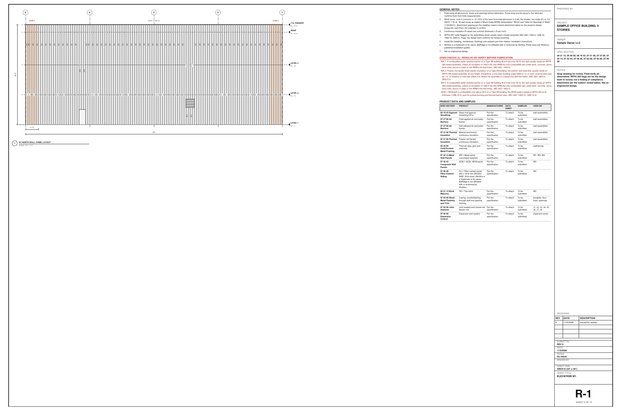
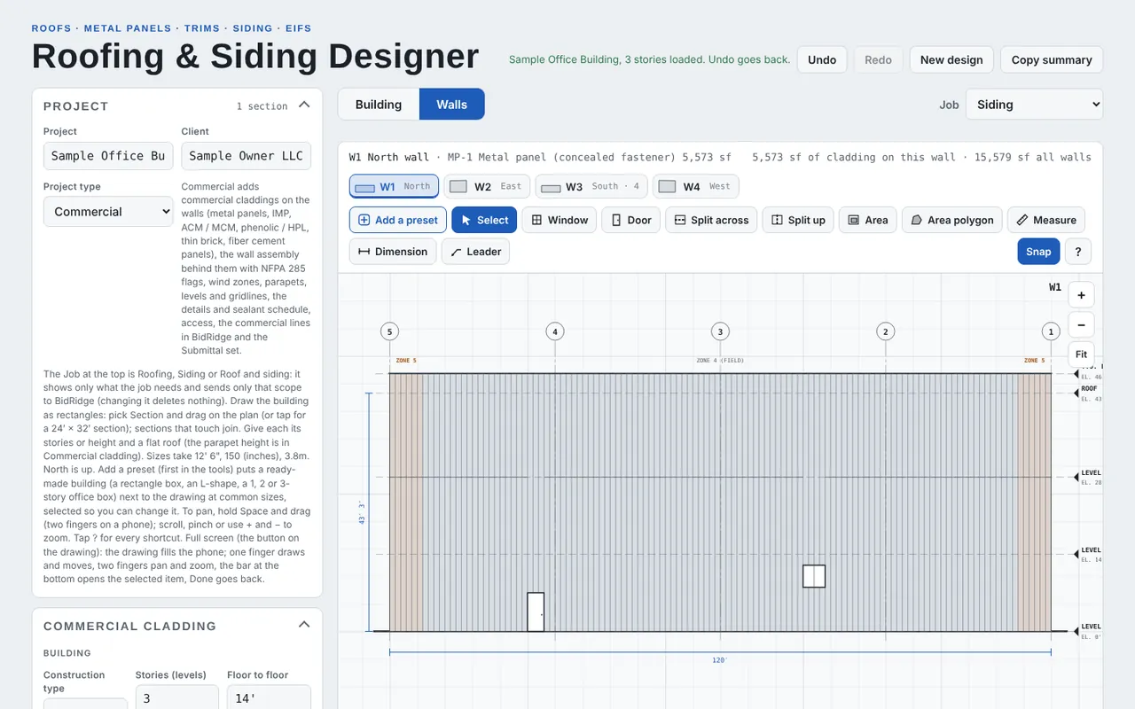
Open the Roofing & Siding Designer, tap New design, then Sample Office Building, 3 stories. The project type is Commercial, so the Commercial cladding card and settings show, and each wall's elevation carries gridlines 1 to 5, the level lines up to the top of the parapet and the wind zone bands. W1, the north wall, is 120 ft of MP-1 metal panels, 5,573 sf net with 2 openings; Building and Walls switch between the plan and the elevations.

Field tip: The sample's names and sizes are made up. Residential projects never show the commercial cards; their roofs and siding are as before.
Step 2: The building in the Roofing & Siding Designer

Step 2: The building

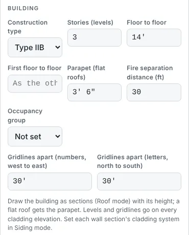
Under Commercial cladding, Building: Type IIB construction, 3 stories at 14 ft floor to floor, a 3' 6" parapet, 30 ft of fire separation distance and gridlines 30 ft apart each way. The construction type and the height (46.8 ft to the top of the parapet here) drive the NFPA 285 flags; the levels and gridlines go on every cladding elevation.

Field tip: Draw the building as sections in Roof mode with its height; a flat roof gets the parapet.

Step 3: The wall assembly in the Roofing & Siding Designer

Step 3: The wall assembly

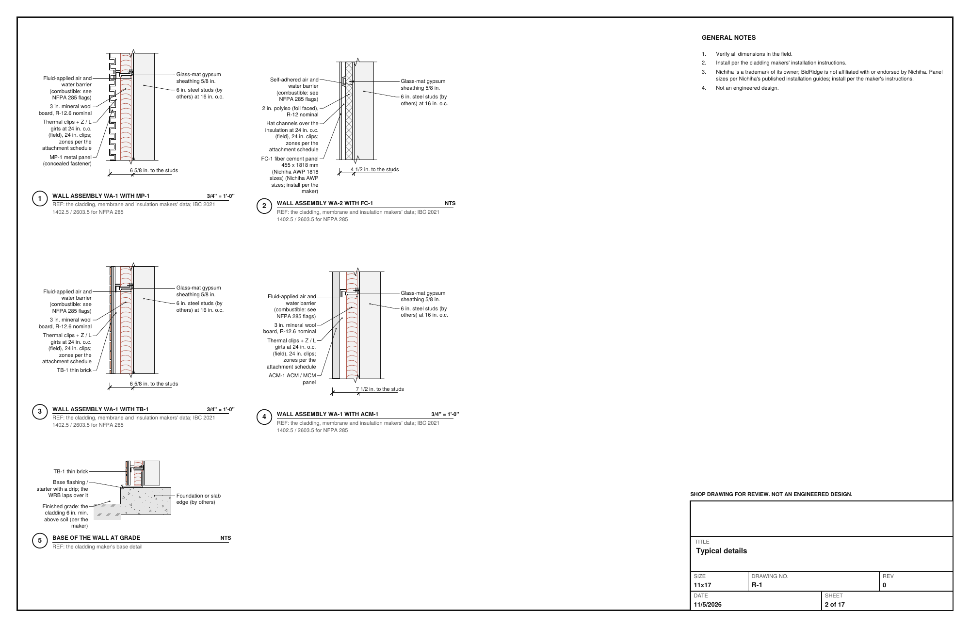
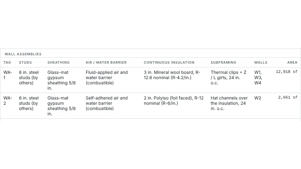
Wall assemblies: what goes behind the cladding. WA-1 (W1, W3, W4, 12,918 sf) is 5/8 in. glass-mat gypsum sheathing, a fluid-applied air and water barrier, 3 in. of mineral wool board (R-12.6 nominal) and thermal clips with Z / L girts 24 in. apart. WA-2 (W2, 2,661 sf) has a self-adhered barrier, 2 in. of foil-faced polyiso (R-12 nominal) and hat channels over the insulation. Each wall picks its assembly; the details draw it.

Field tip: R-values are nominal per inch of the insulation picked; the studs and sheathing behind are by others.

Step 4: NFPA 285 flags by construction type in the Roofing & Siding Designer

Step 4: NFPA 285 flags by construction type

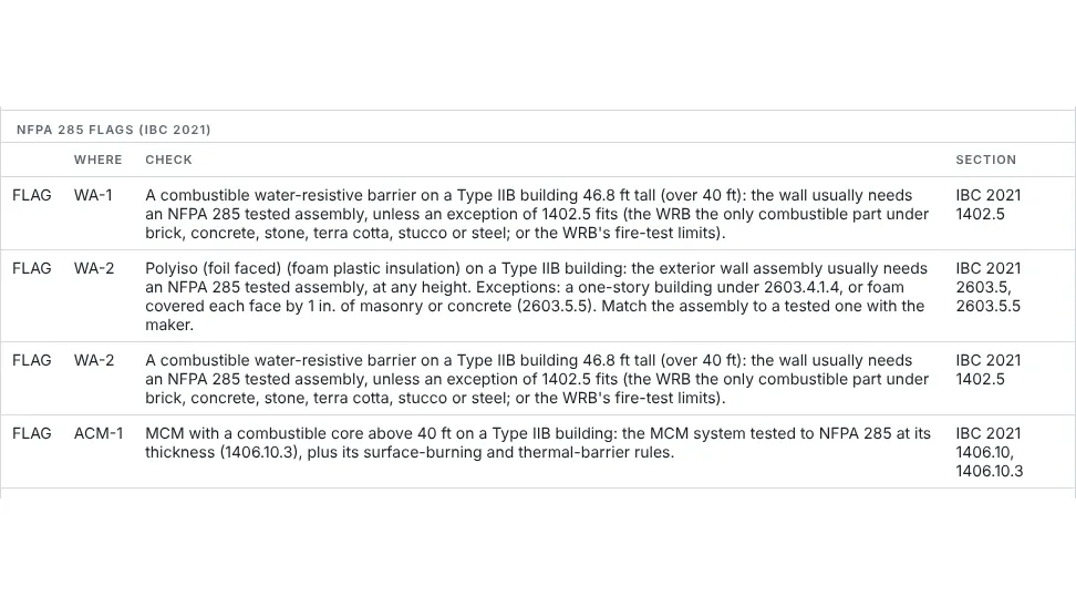
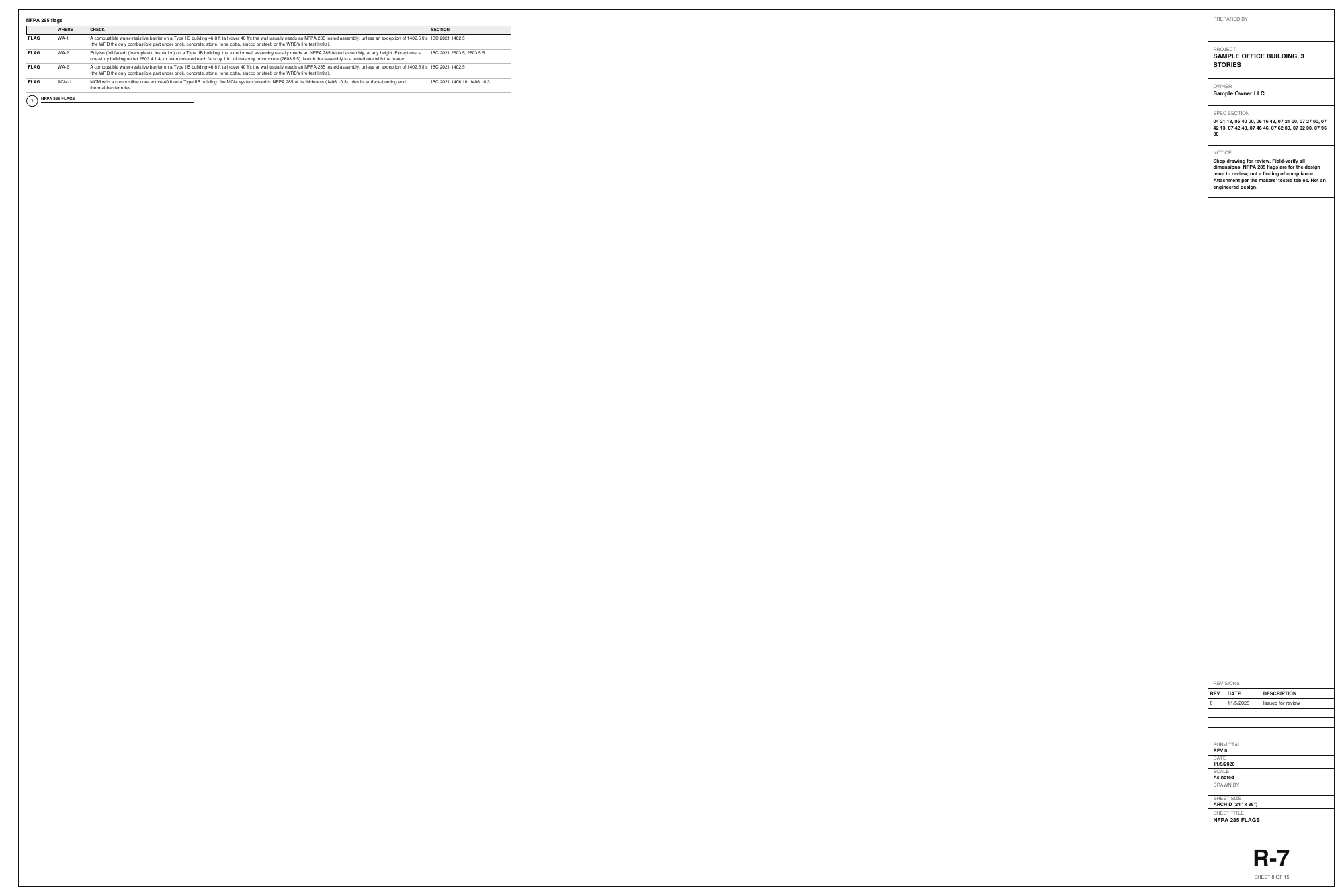
The flags read the IBC 2021 model text against the construction type and height. On this Type IIB building, 46.8 ft tall: a combustible water-resistive barrier over 40 ft on WA-1 and WA-2 (1402.5, with its exceptions), the polyiso foam plastic on WA-2 at any height (2603.5, 2603.5.5), and the ACM with a combustible core above 40 ft (1406.10, 1406.10.3). Four flags, each with its section (the picture), in the checks and on the NFPA 285 flags sheet. The real answer is a tested assembly: type its listing in the assembly's or the system's NFPA 285 tested field and each flag becomes a note to match the installed wall to the listing. The sample marks WA-1, WA-2 and ACM-1 that way, so it opens with nothing flagged.

Field tip: Flags to review with the design team, never a finding that a wall complies: match the wall to a tested assembly with the makers.

Step 5: Cladding systems and panel layout in the Roofing & Siding Designer

Step 5: Cladding systems and panel layout

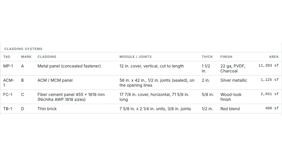
Cladding systems, each with its tag and mark: MP-1 concealed-fastener metal panel, 12 in. cover, vertical, cut to length (11,393 sf); ACM-1, 56 x 42 in. with 1/2 in. sealed joints laid on the opening lines (1,125 sf); FC-1 fiber cement panels in the 455 x 1818 mm size, 17 7/8 in. cover, horizontal (2,661 sf); TB-1 thin brick (400 sf). The layout runs each system across its wall by module and joint and gives each piece a mark.

Field tip: Fiber cement panel sizes per Nichiha's published data; Nichiha is a trademark of its owner, and BidRidge is not affiliated with or endorsed by Nichiha. Install per the maker's instructions.

Step 6: Joint alignment on the elevations in the Roofing & Siding Designer

Step 6: Joint alignment on the elevations

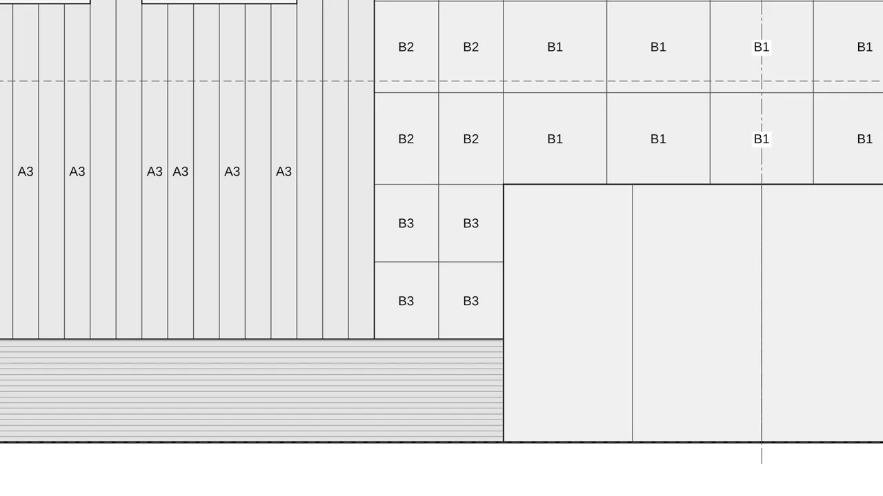
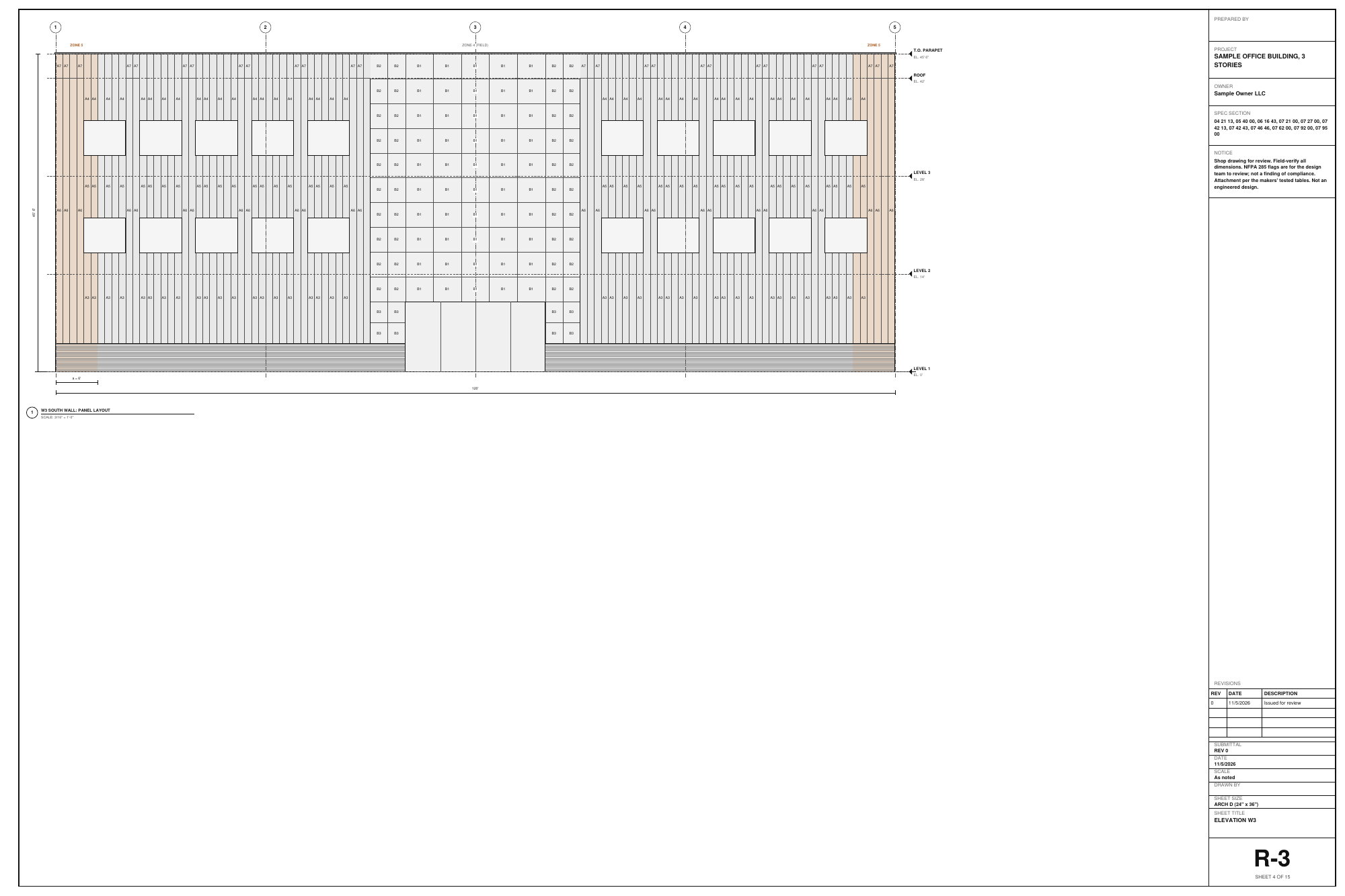
Each elevation sheet draws the panels with their marks, the zone bands, levels and gridlines. On W3, the south wall, the ACM panels at the entry line up with the storefront and the windows above, the metal panels run between them, and the thin brick base wraps the bottom. Where two claddings meet, the transition gets its trim and a J8 sealant joint (196 LF on W3).

Field tip: Joints on the openings line the panel joints up with the window and door edges; the order list shows what it costs in waste.

Step 7: Attachment by wind zone in the Roofing & Siding Designer

Step 7: Attachment by wind zone

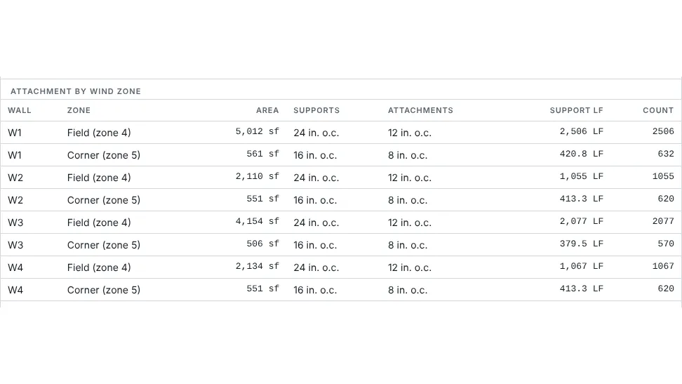
Wind zones and attachment: the least horizontal dimension 60 ft and a mean roof height of 42 ft give a corner band (zone 5) a = 6 ft wide by the ASCE 7-16 chapter 30 wall-zone rule; the rest is field (zone 4). Here the field takes supports 24 in. apart with attachments 12 in. apart and the corners 16 in. and 8 in., wall by wall: on W1, 5,012 sf of field and 561 sf of corner, 2,506 and 632 attachments.

Field tip: The spacing per zone is yours, from the cladding maker's tested attachment tables; past them, the engineer to confirm.

Step 8: Details, joints, trims and flashing in the Roofing & Siding Designer

Step 8: Details, joints, trims and flashing

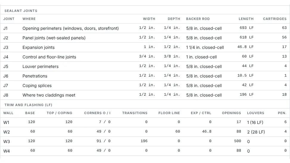
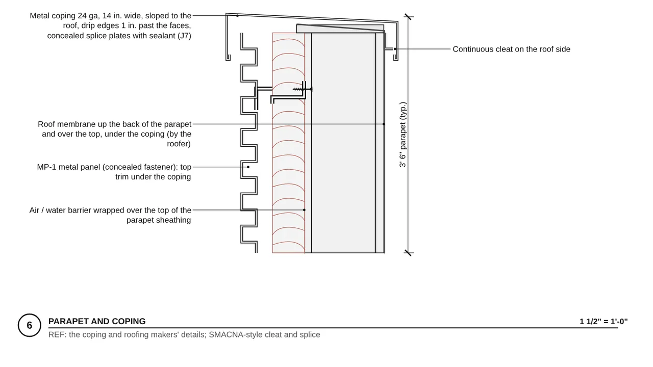
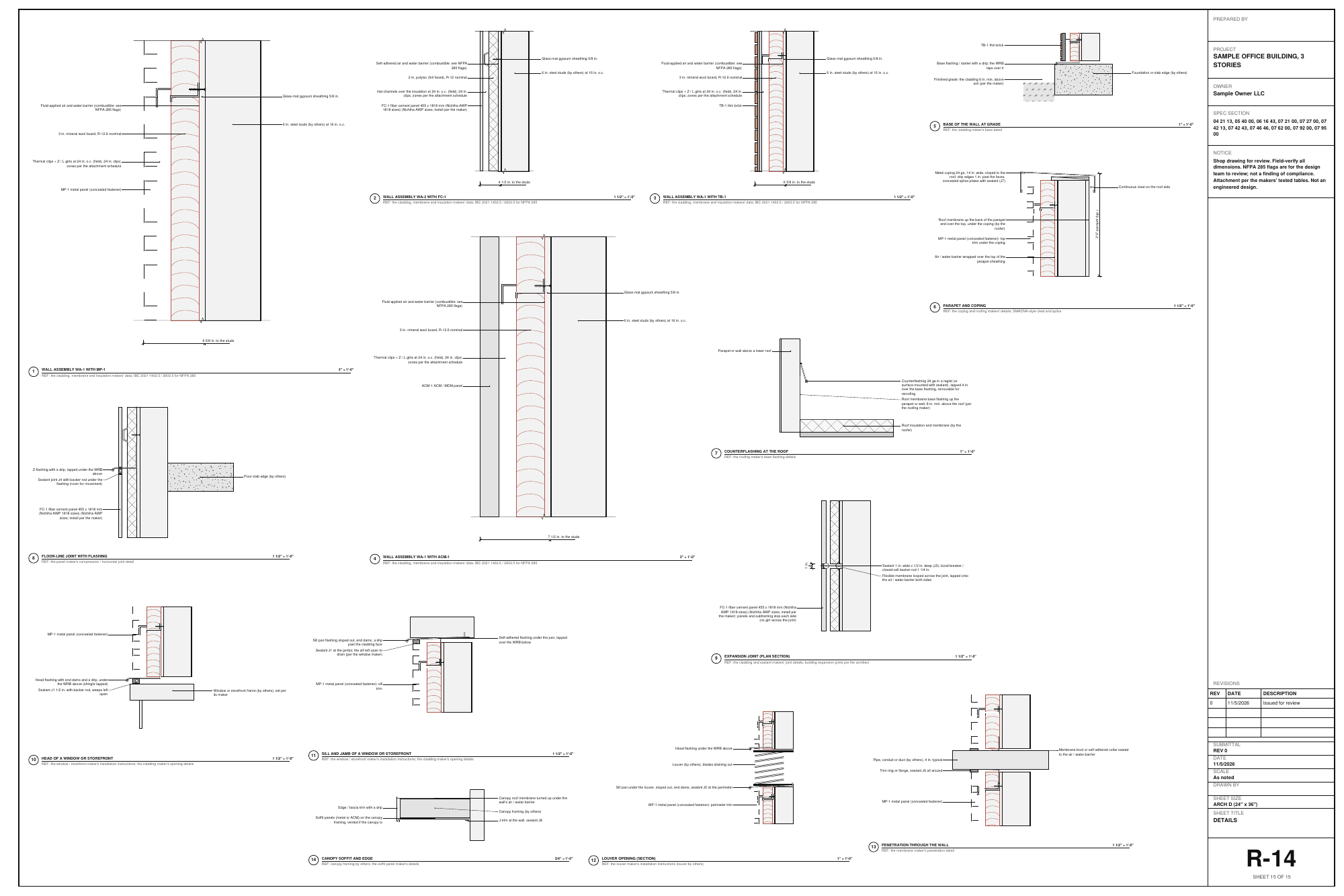
The sealant joint schedule lists each joint by type: J1 opening perimeters 693 LF, J2 wet-sealed panel joints 618 LF, J3 expansion joints 1 in. wide 46.8 LF, J4 control and floor-line joints, louvers, penetrations, coping splices and J8 where two claddings meet: 1,710.3 LF with its backer rod and cartridges. Trim and flashing by wall: base, coping, corners, transitions, floor lines, expansion and control joints, openings, louvers and penetrations. The Details sheet draws 14 of them, from each assembly to the parapet and coping, counterflashing, the floor-line joint, window heads and sills, louvers, penetrations and the canopy soffit.

Field tip: Joint depth is half the width, 1/4 to 1/2 in., on a closed-cell backer rod a size larger than the joint.

Step 9: Import the architect's elevation in the Roofing & Siding Designer

Step 9: Import the architect's elevation

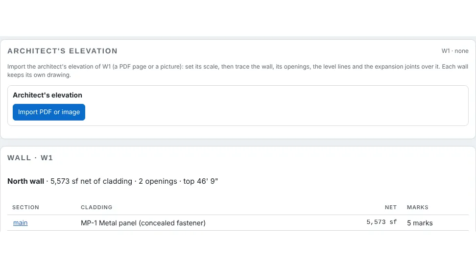
Architect's elevation: Import PDF or image puts the architect's elevation of the selected wall (a PDF page or a picture) under the drawing. Set its scale from a known dimension, then trace the wall, its openings, the level lines and the expansion joints over it. The wall card below sums the result: W1 North wall, 5,573 sf net of cladding, 2 openings, top 46' 9", MP-1 in 5 marks.

Field tip: Each wall keeps its own drawing: import, set the scale, trace, then move on to the next wall.

Step 10: Order list, access and the BidRidge lines in the Roofing & Siding Designer

Step 10: Order list, access and the BidRidge lines

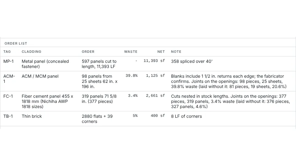
Order list: 597 metal panels cut to length (358 spliced over 40 ft), 98 ACM panels from 25 sheets of 62 x 196 in. (39.8% waste, 20.6% if the joints didn't follow the openings), 319 fiber cement panels nested for 377 pieces (3.4%), 2,880 thin brick flats and 39 corners. Access by elevation picks a boom lift by height, 46 days in all. Send to BidRidge carries the sheathing, barriers, insulation, clips and girts, panels, trims, sealant and access as commercial answers on the Siding scope, with the assemblies and the NFPA 285 notes in its notes.

Field tip: Access days use the crew rates under Commercial cladding: starting figures, set yours.

Step 11: Commercial standing seam metal roofs in the Roofing & Siding Designer

Step 11: Commercial standing seam metal roofs

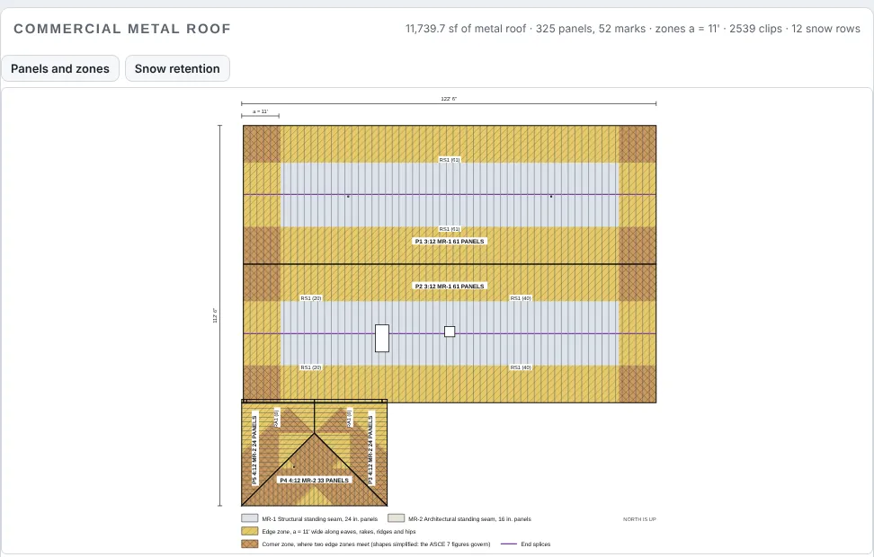
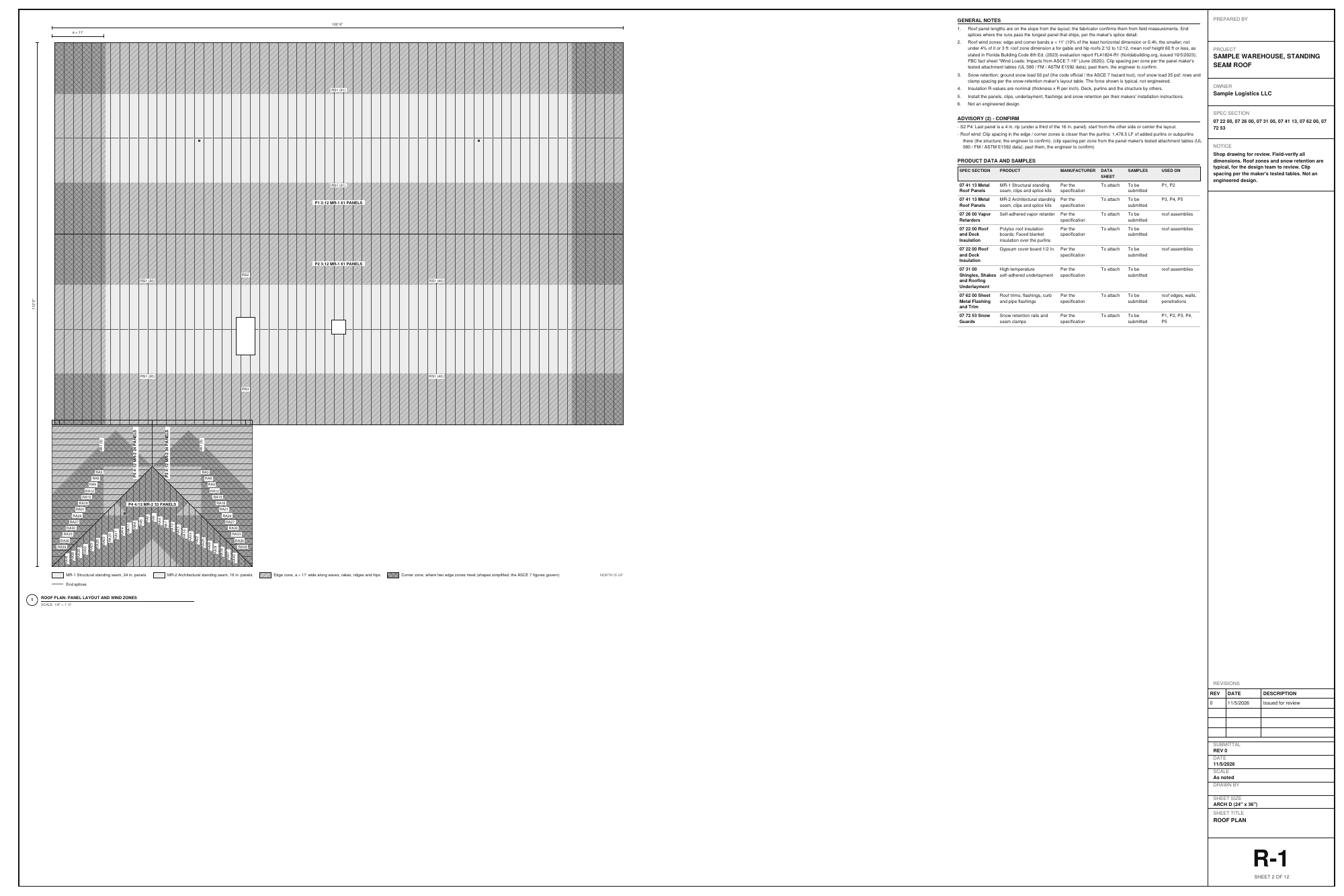
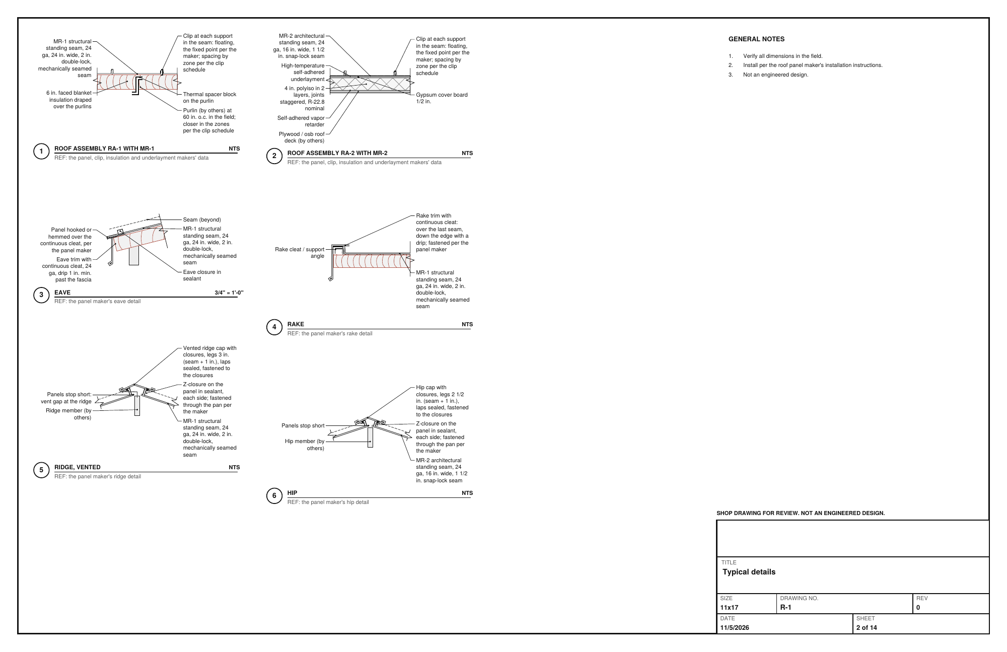
New design, Sample Warehouse, standing seam roof: a 120 x 80 ft 3:12 gable in MR-1, structural standing seam 24 in. wide with a 2 in. double-lock seam over purlins 60 in. apart (10,311.9 sf), and a 4:12 hip office wing in MR-2, architectural standing seam 16 in. wide snap-lock on a solid deck (1,427.8 sf). The Commercial metal roof card draws the panels with their marks, the end splices and the edge and corner zones, a = 11 ft: 11,739.7 sf, 325 panels, 52 marks.

Field tip: Low-slope membrane roofs stay in the low-slope sections; the zone shapes are simplified, the ASCE 7 figures govern.

Step 12: Roof wind zones and clip spacing in the Roofing & Siding Designer

Step 12: Roof wind zones and clip spacing

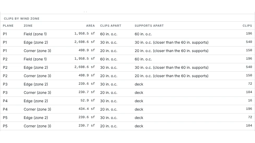
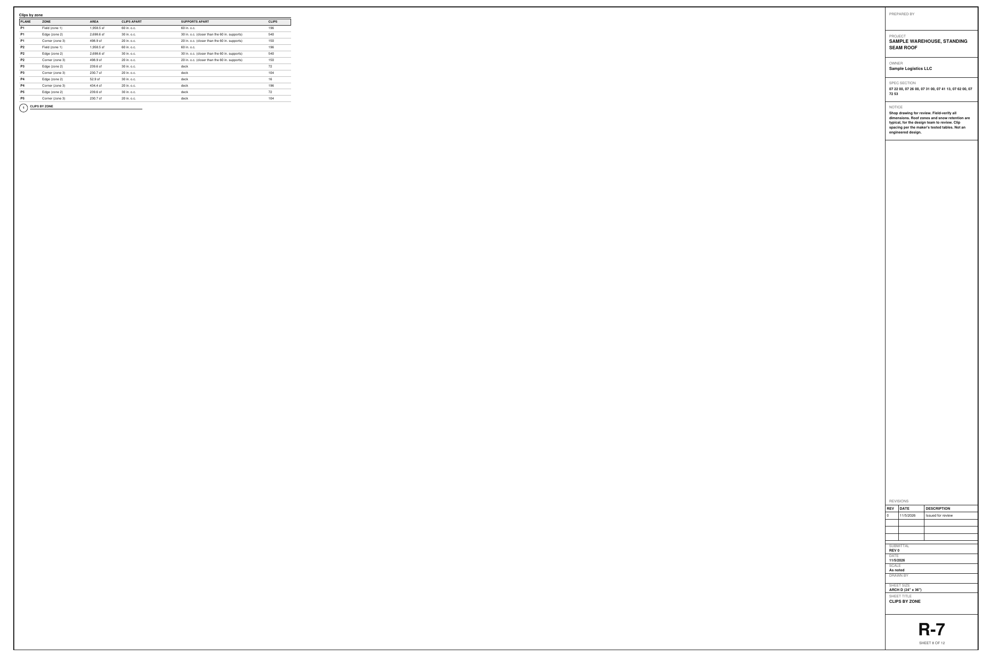
Clips by wind zone: the field (zone 1) at 60 in., the edge (zone 2) at 30 in. and the corners (zone 3) at 20 in., plane by plane: 2,539 clips. Where the clips are closer than the 60 in. purlins, the check asks for 1,478.5 LF of added purlins or subpurlins in the edge and corner zones, for the engineer to confirm. Runs past the longest panel that ships get 121 end splices with 6 in. laps.

Field tip: Clip spacing per zone comes from the panel maker's tested attachment tables (UL 580 / FM / ASTM E1592 data); past them, the engineer to confirm.

Step 13: Snow retention by snow load in the Roofing & Siding Designer

Step 13: Snow retention by snow load

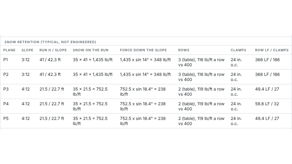
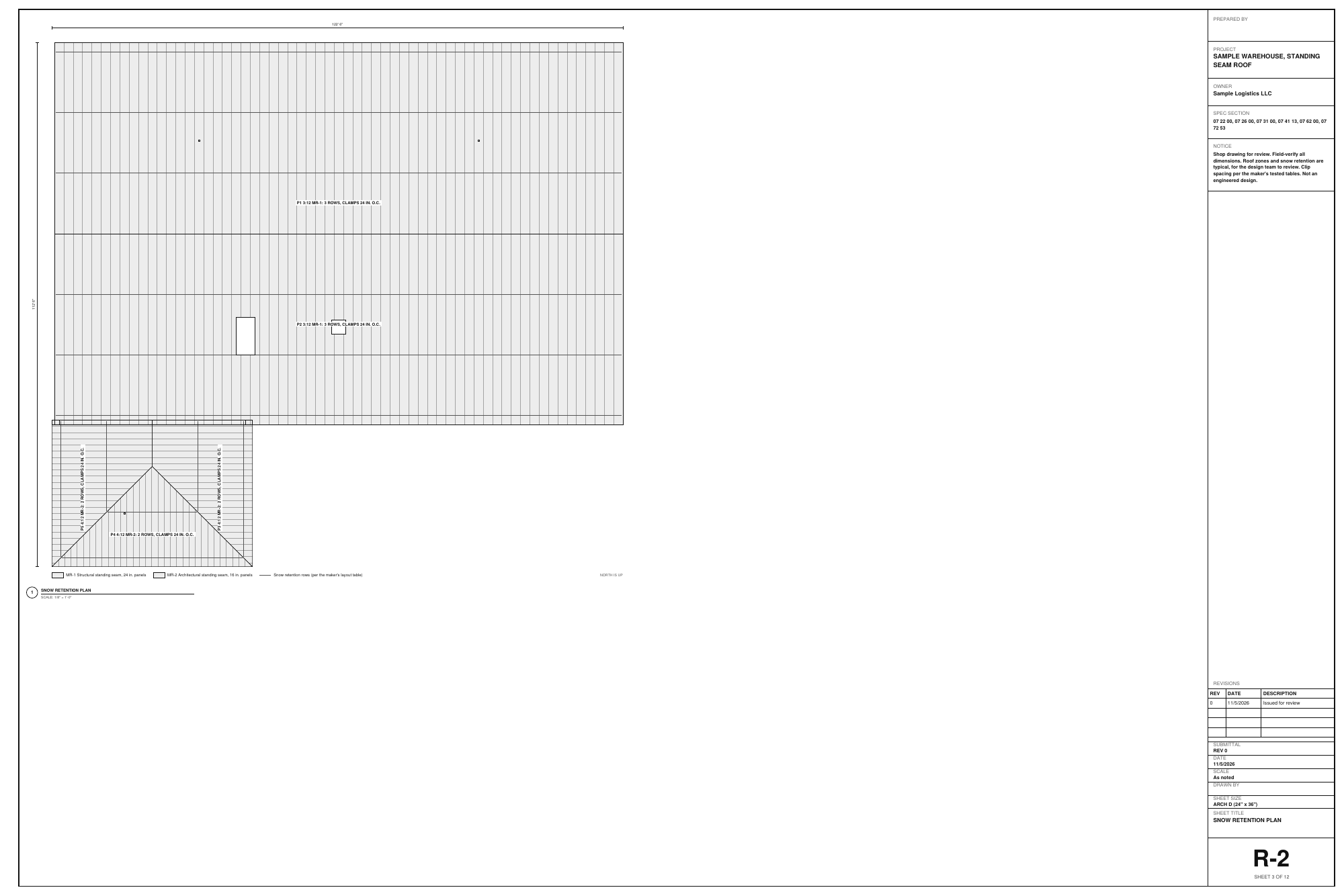
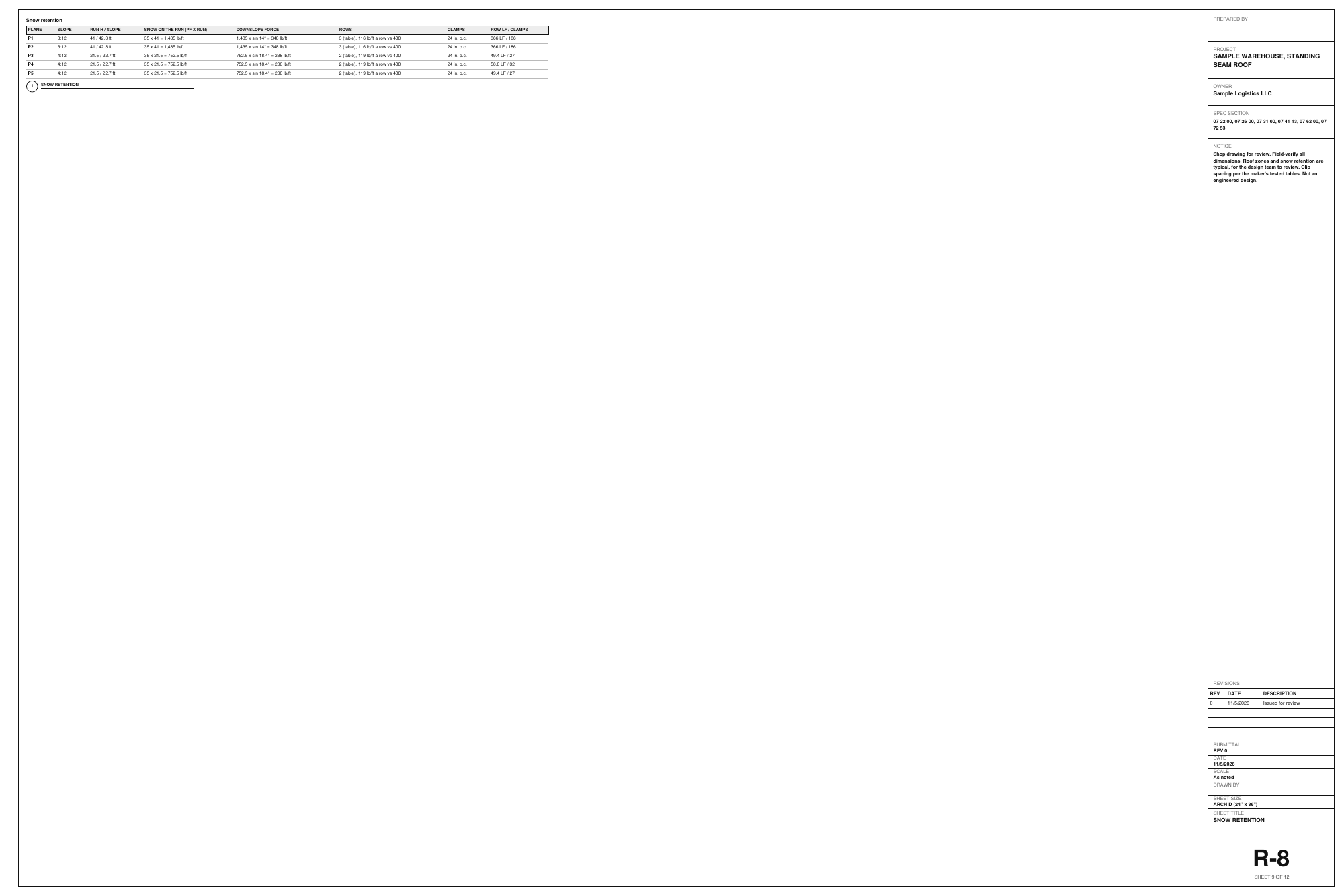
Snow retention works the force down each plane: the 35 psf roof snow load (per the drawings; ground snow 50 psf per the code official) times the horizontal run, times the sine of the slope. On the 3:12 planes that is 35 x 41 = 1,435 lb/ft and 348 lb/ft down the slope: 3 rows at 116 lb/ft a row against 400, clamps 24 in. apart, 366 LF and 186 clamps a plane. The 4:12 wing planes take 2 rows: 12 rows in all, drawn on the snow retention plan.

Field tip: Typical, not engineered: the rows and clamp spacing come from the snow-retention maker's layout table.

Step 14: Roof trims and flashings in the Roofing & Siding Designer

Step 14: Roof trims and flashings

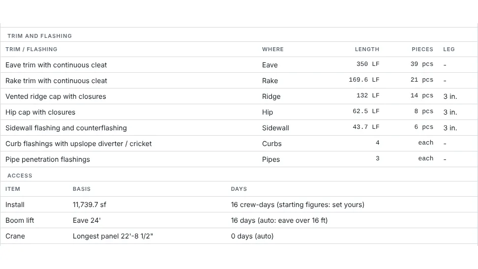
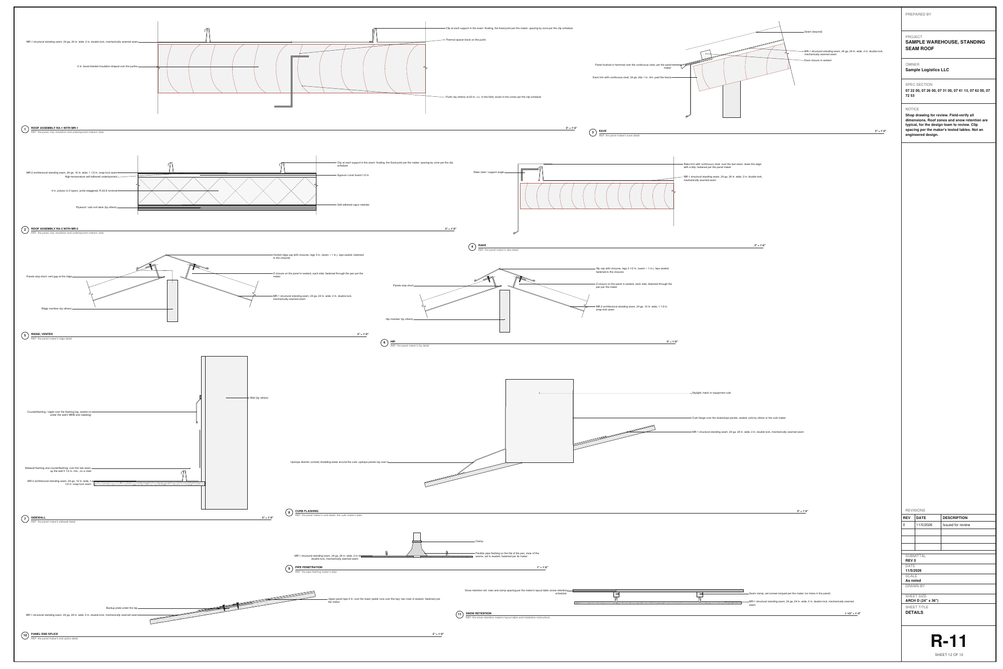
Trim and flashing: 350 LF of eave trim and 169.6 LF of rake trim on continuous cleats, 132 LF of vented ridge cap and 62.5 LF of hip cap with closures, 43.7 LF of sidewall flashing and counterflashing where the wing meets the warehouse, 4 curb flashings with diverters and 3 pipe flashings, each with its pieces. Access: 16 crew-days to install and a boom lift for the 24 ft eave.

Field tip: The roof details draw the eave, rake, ridge and hip with the panel maker's details referenced.

Step 15: The Submittal sets in the Roofing & Siding Designer

Step 15: The Submittal sets

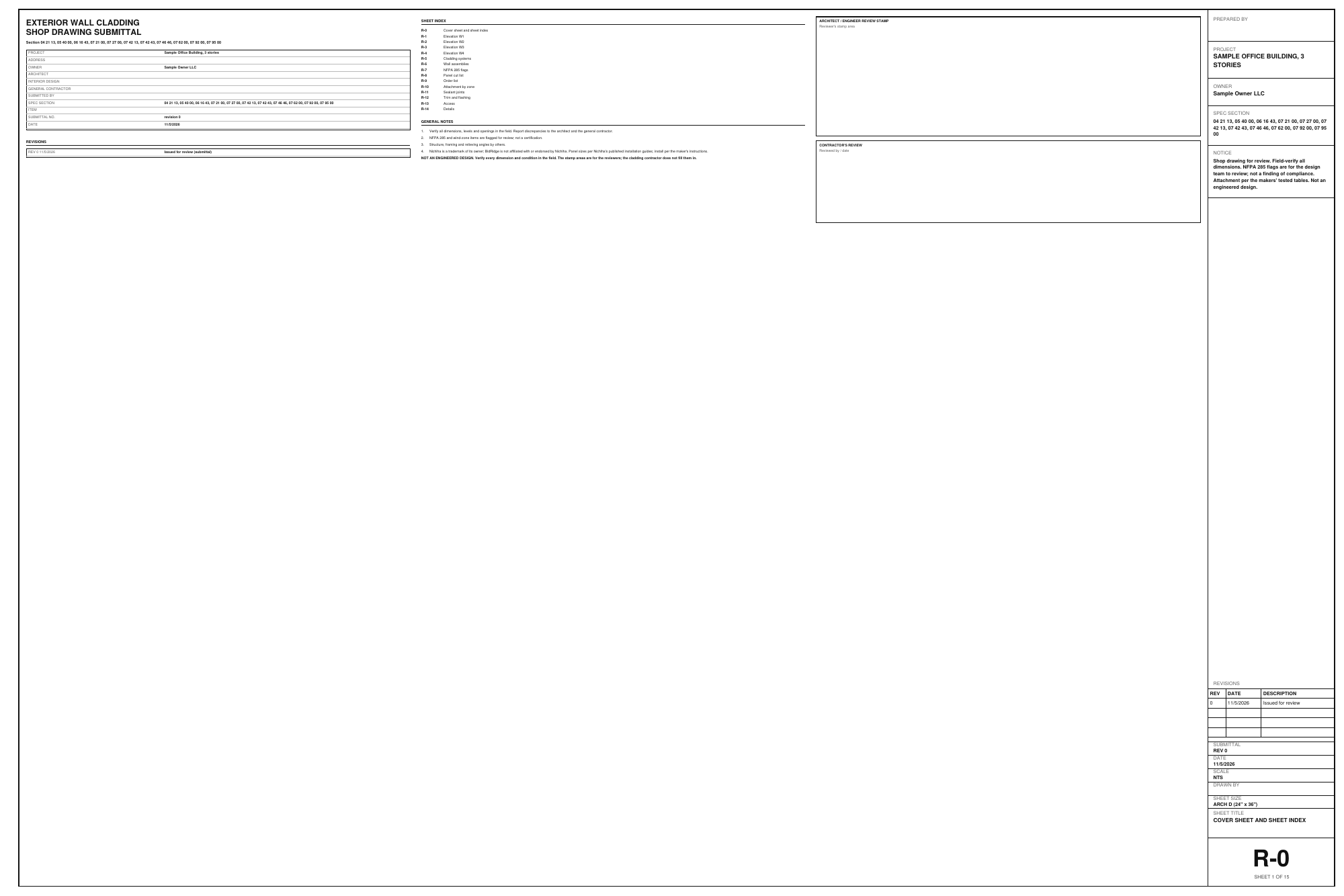
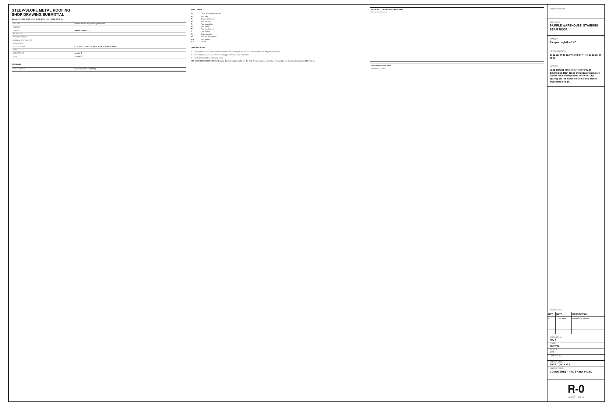
Drawing set, Sheets for: Submittal set. The office walls on ARCH D take 15 sheets: R-0 Cover, R-1 to R-4 the four elevations, R-5 Cladding systems, R-6 Wall assemblies, R-7 NFPA 285 flags, R-8 Panel cut list, R-9 Order list, R-10 Attachment by zone, R-11 Sealant joints, R-12 Trim and flashing, R-13 Access and R-14 Details. The warehouse roof on ARCH D takes 12: R-1 Roof plan, R-2 Snow retention plan, the roof schedules, R-6 Roof panel cut list, R-7 Clips by zone, R-8 Snow retention, R-9 Roof trim and flashing, R-10 Roof access and R-11 Details; its 11x17 shop set has 14, typical details first.

Field tip: The Submittal set is download only: Save PDF. It is never added to the BidRidge job.

What you get

The drawing set, the lists and the files

Real files from this sample, made by the designer. Tap a page to see it full size. Yours carry your company, the client and the address.

R-0 Cover sheet and sheet index
R-1 Elevation W1 with the general notes and product data
R-3 Elevation W3: panel layout
R-7 NFPA 285 flags
R-7 NFPA 285 flags
R-14 Details
R-14 Details
Walls Submittal (11x17 shop) R-1 Typical details
Roof Submittal R-0 Cover sheet and sheet index
Roof R-1 Roof plan: panel layout and wind zones
Roof R-2 Snow retention plan
Roof R-7 Clips by zone
Roof R-8 Snow retention
Roof R-11 Details
Roof R-11 Details
Roof Submittal (11x17 shop) R-1 Typical details

More in the guide

Try it on your own job

Open the sample, change it to your measurements, and send it to a BidRidge quote. Drawing is free; the drawing set, the lists and the quote come with a BidRidge license or the 14-day trial.

In the Roofing & Siding Designer, tap Open project and pick the sample file: it opens as the office building's walls in this chapter. The metal roofs are the designer's Sample Warehouse, standing seam roof (New design).

Sample designs: names, sizes and clients are made up. Prices are BidRidge's starting rates; set your own. The designers check against common guidelines (IRC, NKBA and the makers' published numbers) to help you catch mistakes. They don't replace your building department or the manufacturer's installation instructions: verify with them.