BidRidge › Designers › Guide › Chapter 32

Chapter 32 · Concrete DesignerBeta

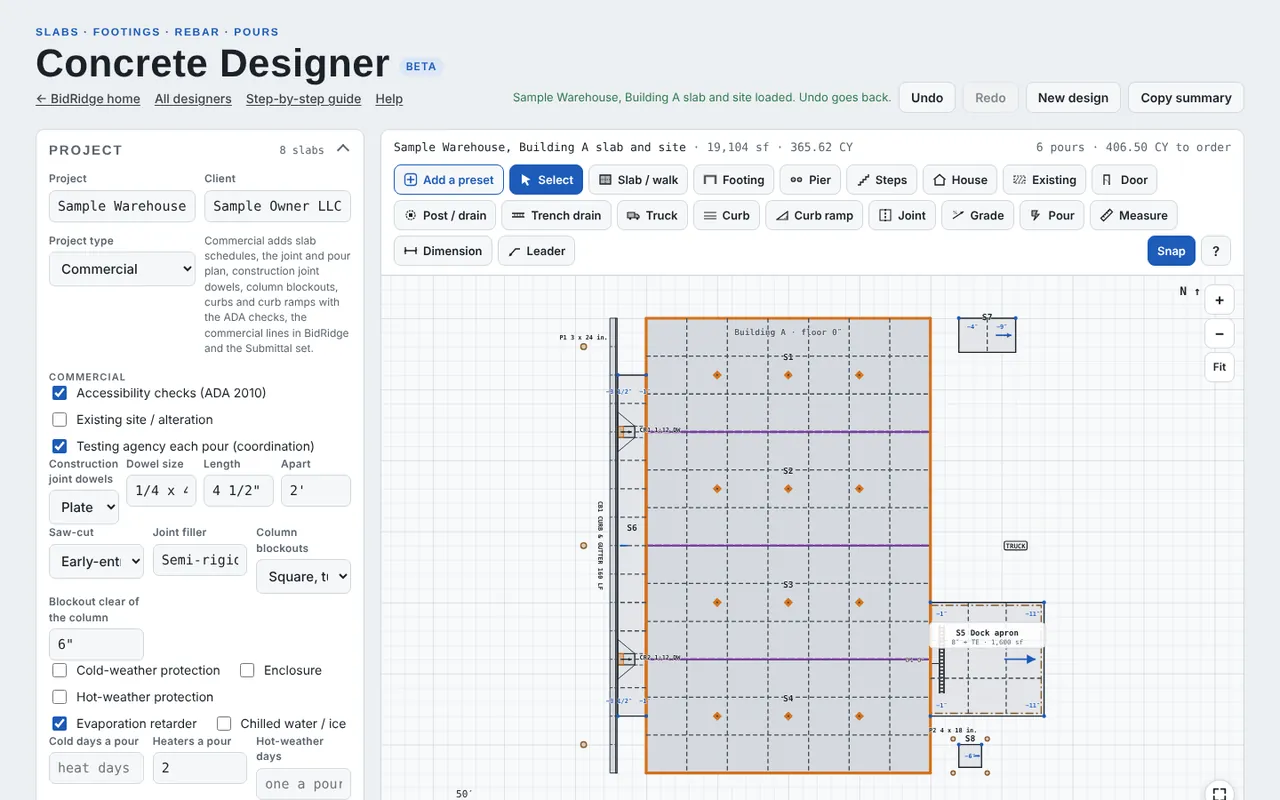
Sample Warehouse, Building A slab and site: a 100 x 160 ft slab in four pour strips, the dock apron, sidewalk, curb and gutter and two curb ramps

From the designer's commercial sample: a 6 in. building slab poured in four 4,000 sf strips with plate dowels at the construction joints, early-entry saw cuts and diamond blockouts at the columns, a cooler depression and floor flatness numbers; outside, the dock apron, the front sidewalk, curb and gutter, two curb ramps, a dumpster pad, a transformer pad, light pole bases and bollards. Six pours with their trucks, pump and testing; the accessibility checks with their ADA sections; the commercial lines for the BidRidge quote; and the Submittal set.

In the Concrete Designer, tap Open project and pick the sample file: it opens as the warehouse slab and site in this chapter.

Narrated walkthrough, 2:04. Captions on.

The sample in numbers

  • Flatwork
    19,104 sf
    8 slabs · 4 building strips of 4,000 sf
  • Concrete
    406.50 CY
    to order in 6 pours, 42 trucks, pumped
  • Joints
    2,042 LF
    sawn early-entry · 150 dowels · 711.6 LF isolation
  • Site
    2 curb ramps
    160 LF curb and gutter · 3 pole bases · 4 bollards
  • Sheets
    9
    Submittal set, ARCH D (11 shop sheets)

Step by step

Step 1: Open the commercial sample in the Concrete Designer

Step 1: Open the commercial sample

Open the Concrete Designer, tap New design, then Sample Warehouse, Building A slab and site. Its Project type is Commercial, so the slab, joint, pour and site concrete schedules, the joint and pour plan, construction joint dowels, column blockouts, curbs and curb ramps with the ADA checks, the commercial lines and the Submittal set show. The building slab is 100 x 160 ft in four pour strips, S1 to S4; outside are the dock apron (S5), the front sidewalk (S6), the dumpster and transformer pads (S7, S8), the curb and gutter (CB1), two curb ramps, the light pole bases and the bollards.

Field tip: The sample's names and sizes are made up. Everything stays editable.
Step 2: The commercial settings in the Concrete Designer

Step 2: The commercial settings

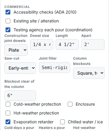
Under Project, Commercial: Accessibility checks (ADA 2010) and Testing agency each pour (coordination) are on; Existing site / alteration is off. The construction joints get plate dowels (1/4 x 4 1/2 in., length 4 1/2") 2' apart; the saw-cut is early-entry (1 to 4 h after finishing); the joint filler is semi-rigid joint filler (per the specs); column blockouts are square, turned 45°, 6" clear of the column. Cold- and hot-weather protection, an enclosure, the evaporation retarder and chilled water are there when the pours need them.

Field tip: These are starting points: the structural drawings and the specifications govern the joints, dowels and protection.

Step 3: The slab schedule in the Concrete Designer

Step 3: The slab schedule

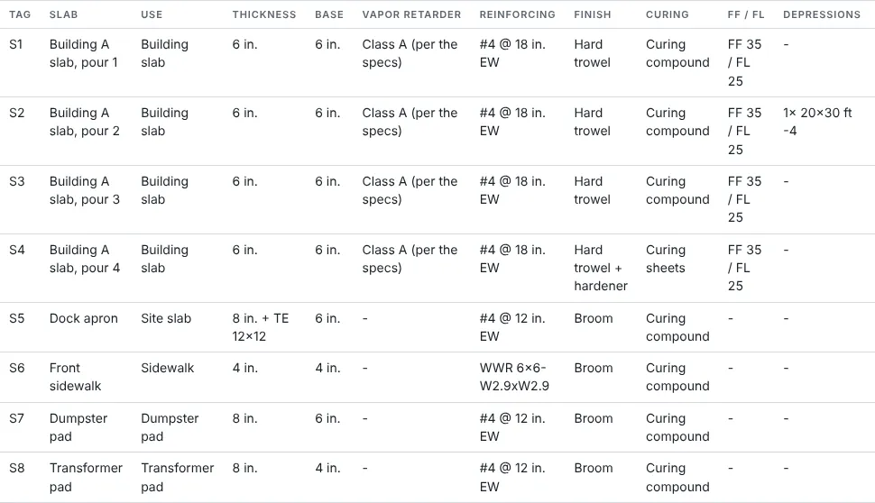
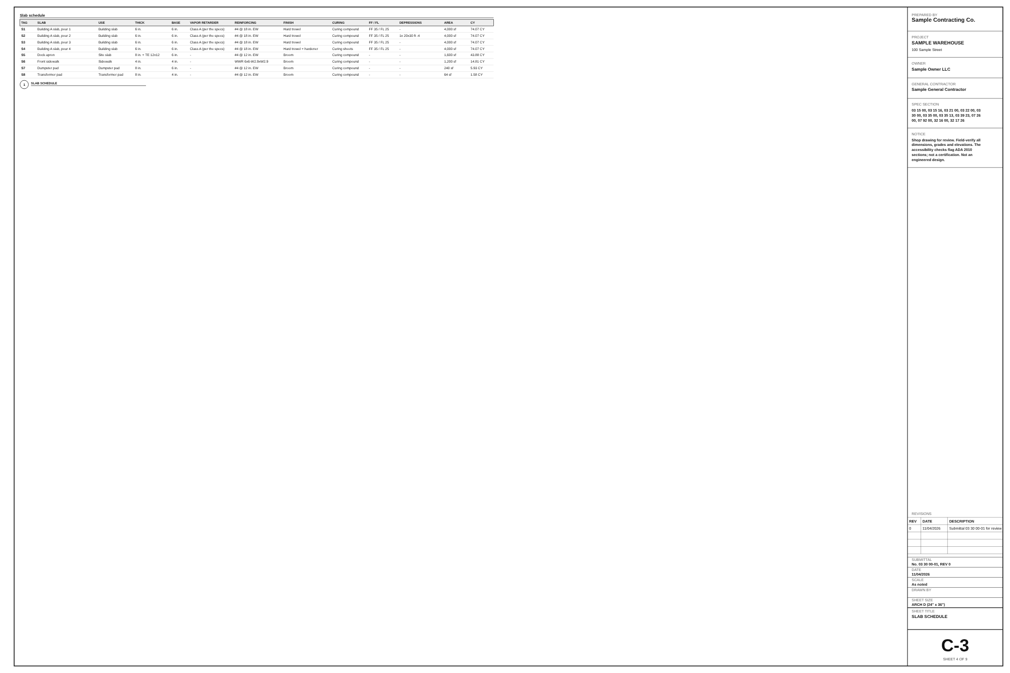
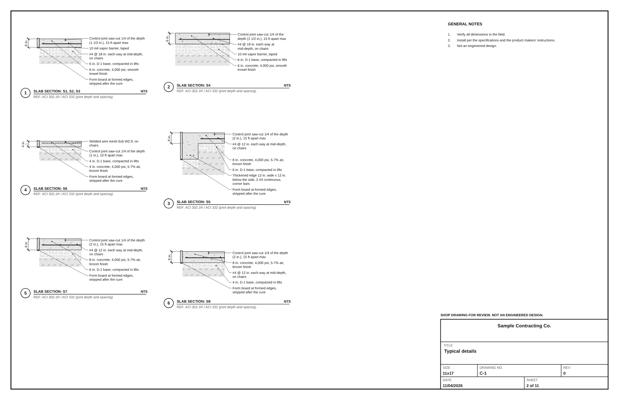
Commercial: slabs, joints, pours and site, Slab schedule: each slab with its tag, use, thickness, base, vapor retarder, reinforcing, finish, curing, FF / FL, depressions, area and yards. S1 to S4 are 6 in. on a 6 in. base with a Class A vapor retarder, #4 at 18 in. each way, hard trowel, FF 35 / FL 25; S2 has a 20 x 30 ft depression 4 in. down for the cooler, and S4 a hardener with curing sheets. The dock apron is 8 in. with a 12 x 12 thickened edge, the sidewalk 4 in. on welded wire.

Field tip: FF/FL numbers come from the specification; the designer carries them to the schedule and the quote.

Step 4: The joint layout in the Concrete Designer

Step 4: The joint layout

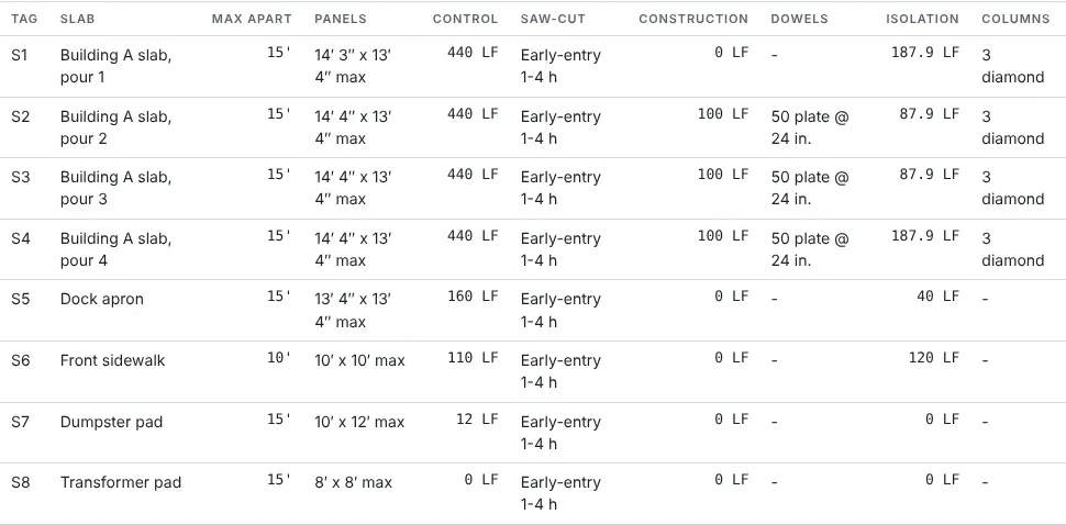
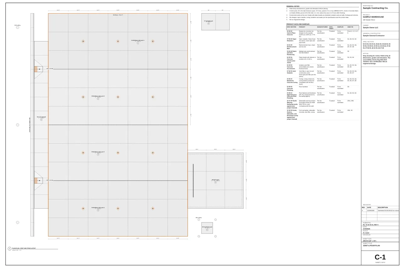
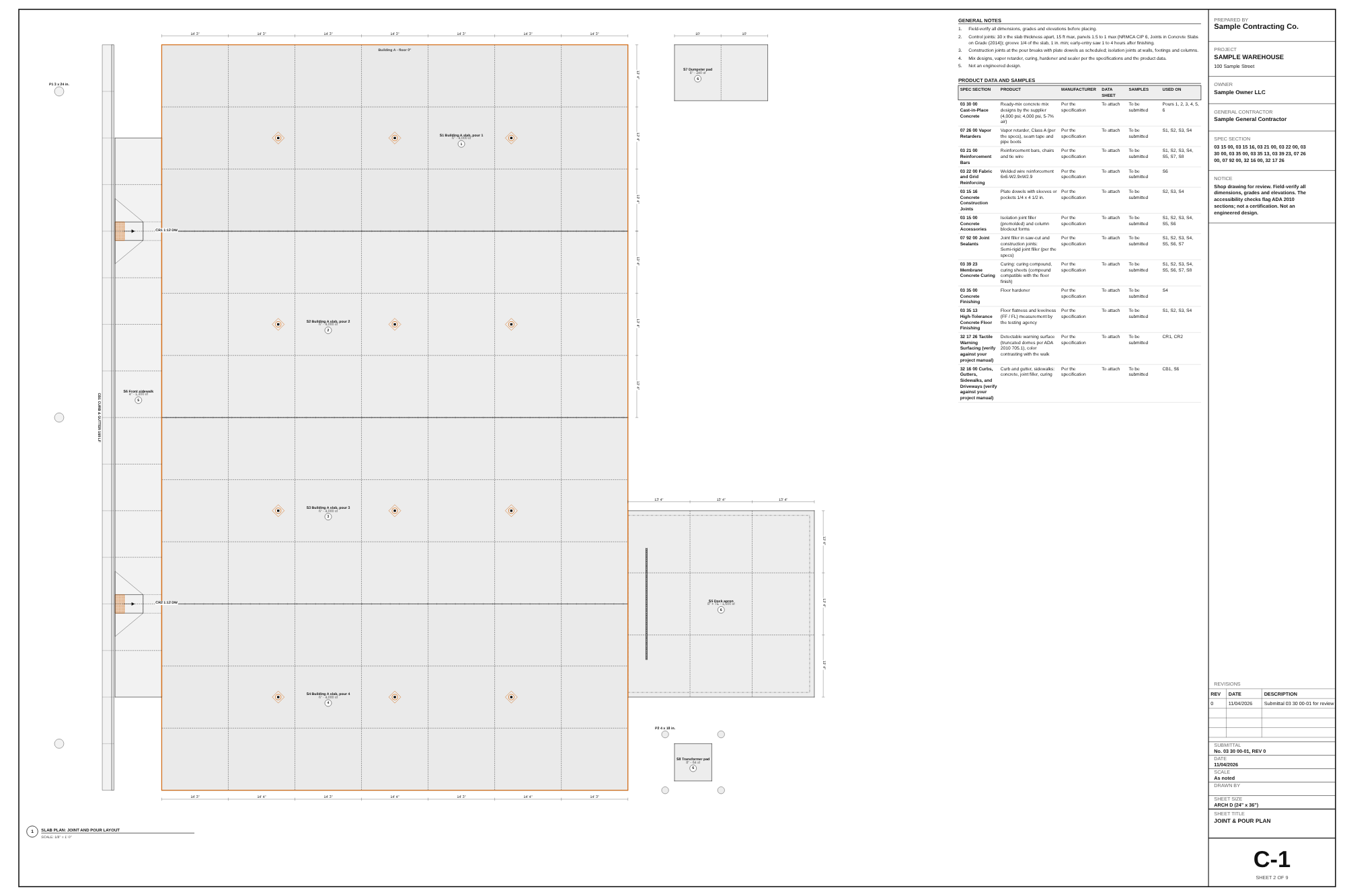
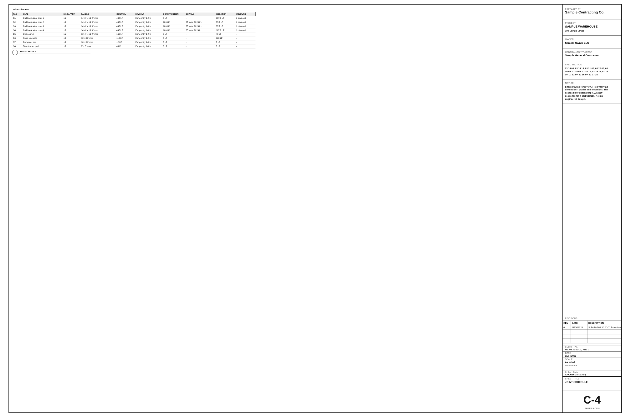
Joints are laid out at most 15 ft apart in the 6 in. slabs (10 ft in the sidewalk), panels no longer than 1.5 times their width: 14′ 4″ x 13′ 4″ at most here, 440 LF of sawn control joints a strip. The strips meet at construction joints with 50 dowels each (100 LF), isolation joints run at the walls, and each strip has 3 diamond blockouts at its columns. The joint schedule and the Joint & pour plan list them: 2,042 LF of control joints and 711.6 LF of isolation.

Field tip: Joint spacing follows the NRMCA rule of thumb (24 to 36 times the thickness, 15 ft at most, panels no longer than 1.5 times their width); move any joint on the plan.

Step 5: The pour plan in the Concrete Designer

Step 5: The pour plan

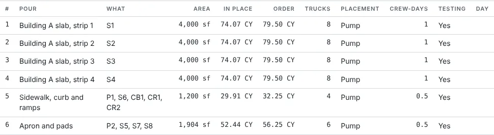
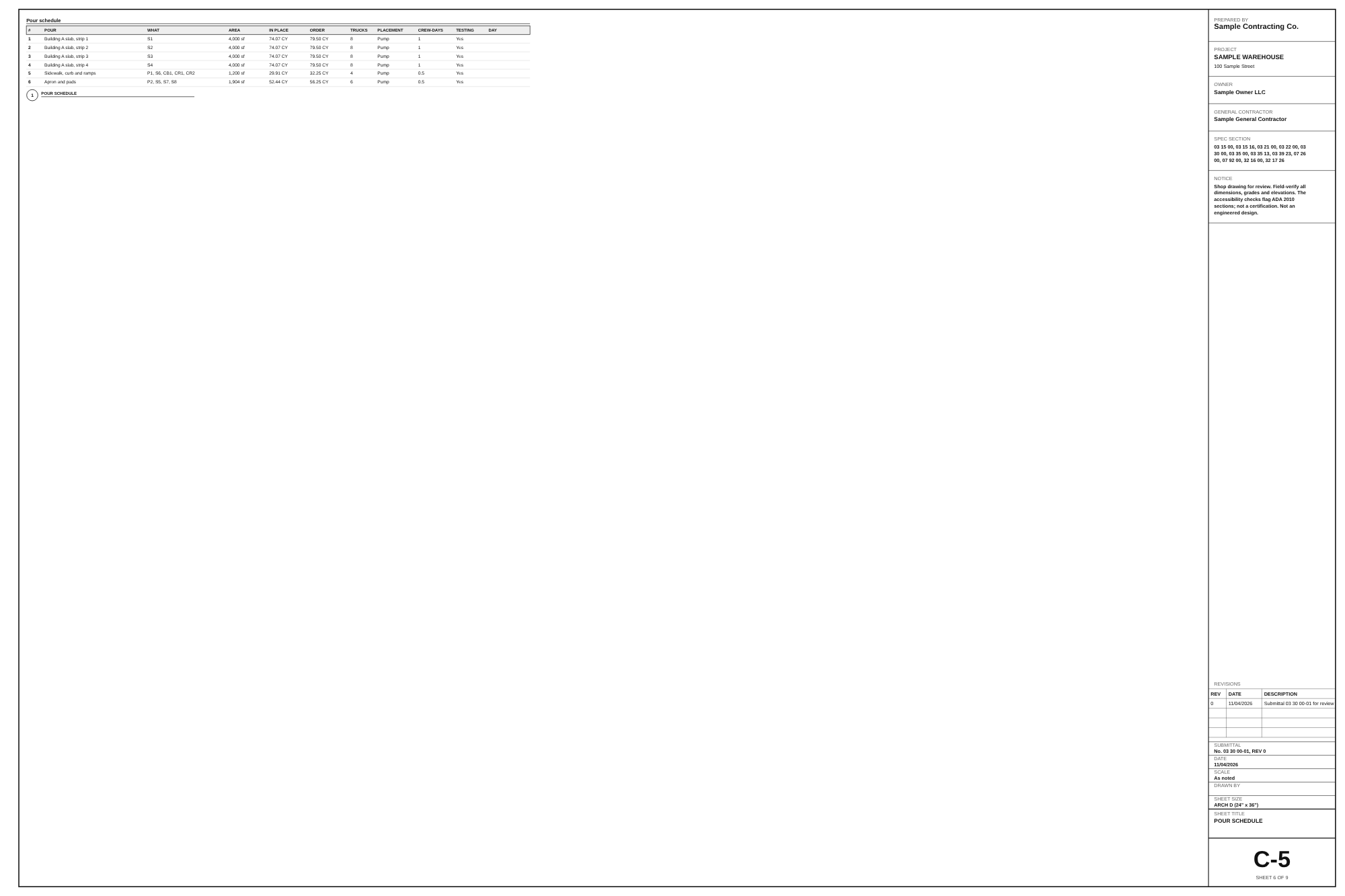
Six pours: each building strip is 74.07 CY in place, 79.50 CY to order (7% waste), 8 trucks, pumped, a crew-day; pour 5 is the sidewalk, curb and ramps with the pole bases (32.25 CY) and pour 6 the apron and pads with the bollards (56.25 CY), half a crew-day each. The testing agency is at every pour. In all, 406.50 CY to order in 42 trucks; each pour has its ready-mix order sheet in the drawing set.

Field tip: Each pour is rounded up to the 1/4 CY after the waste; a pour under the plant's minimum is flagged for a short-load fee.

Step 6: Site concrete in the Concrete Designer

Step 6: Site concrete

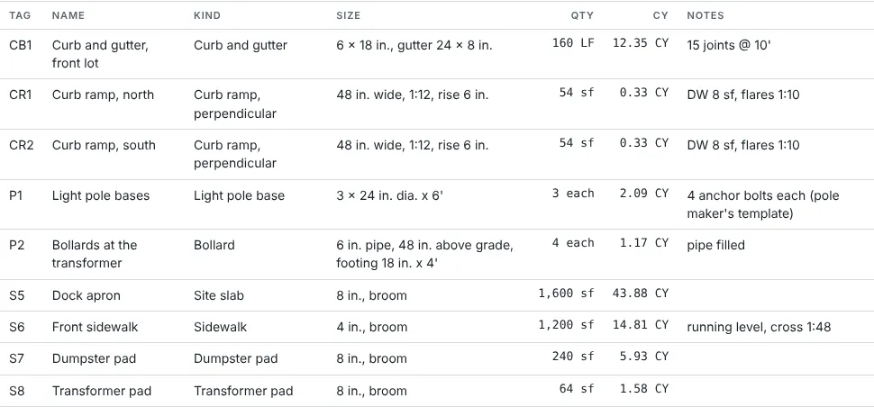
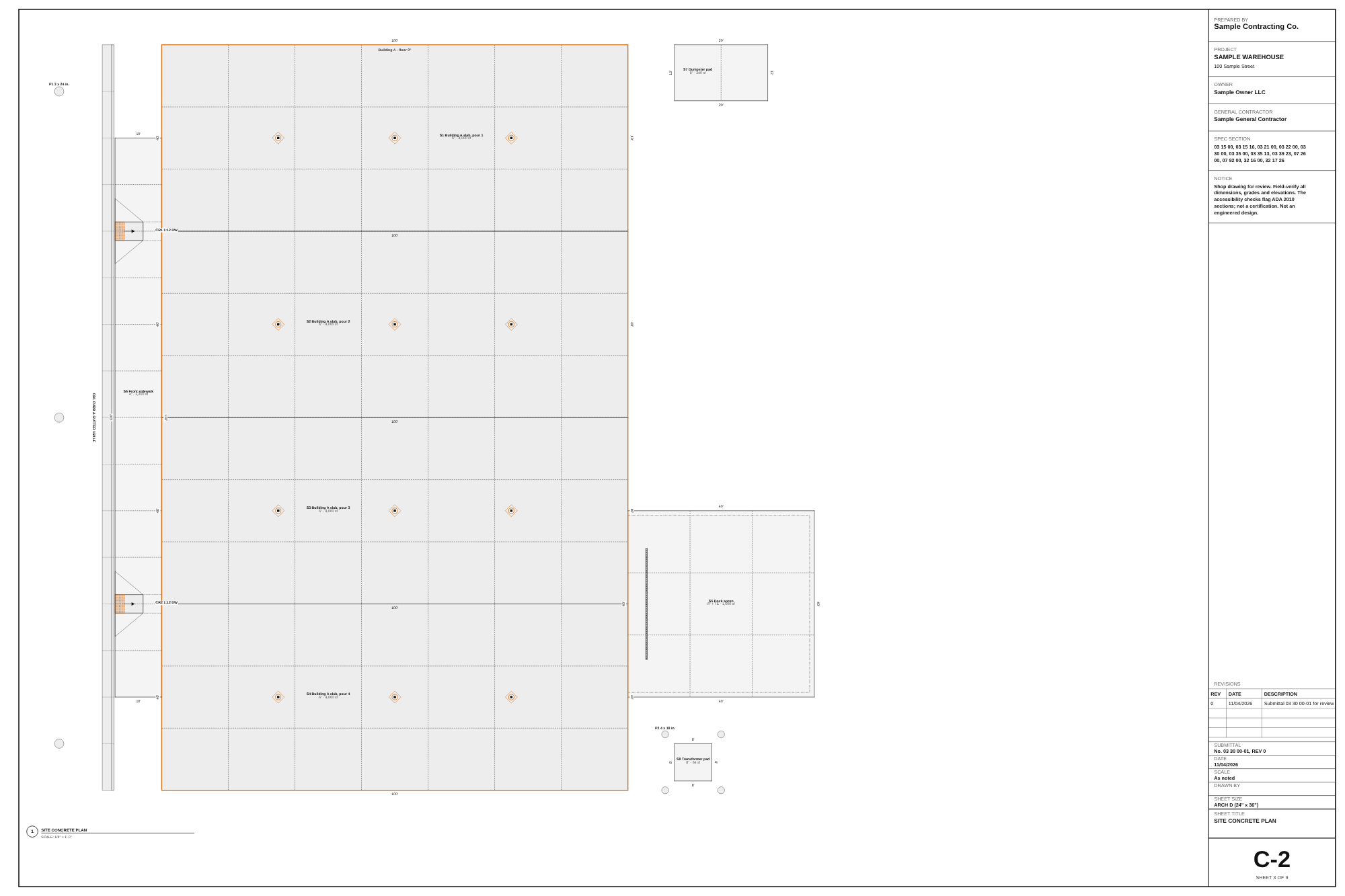
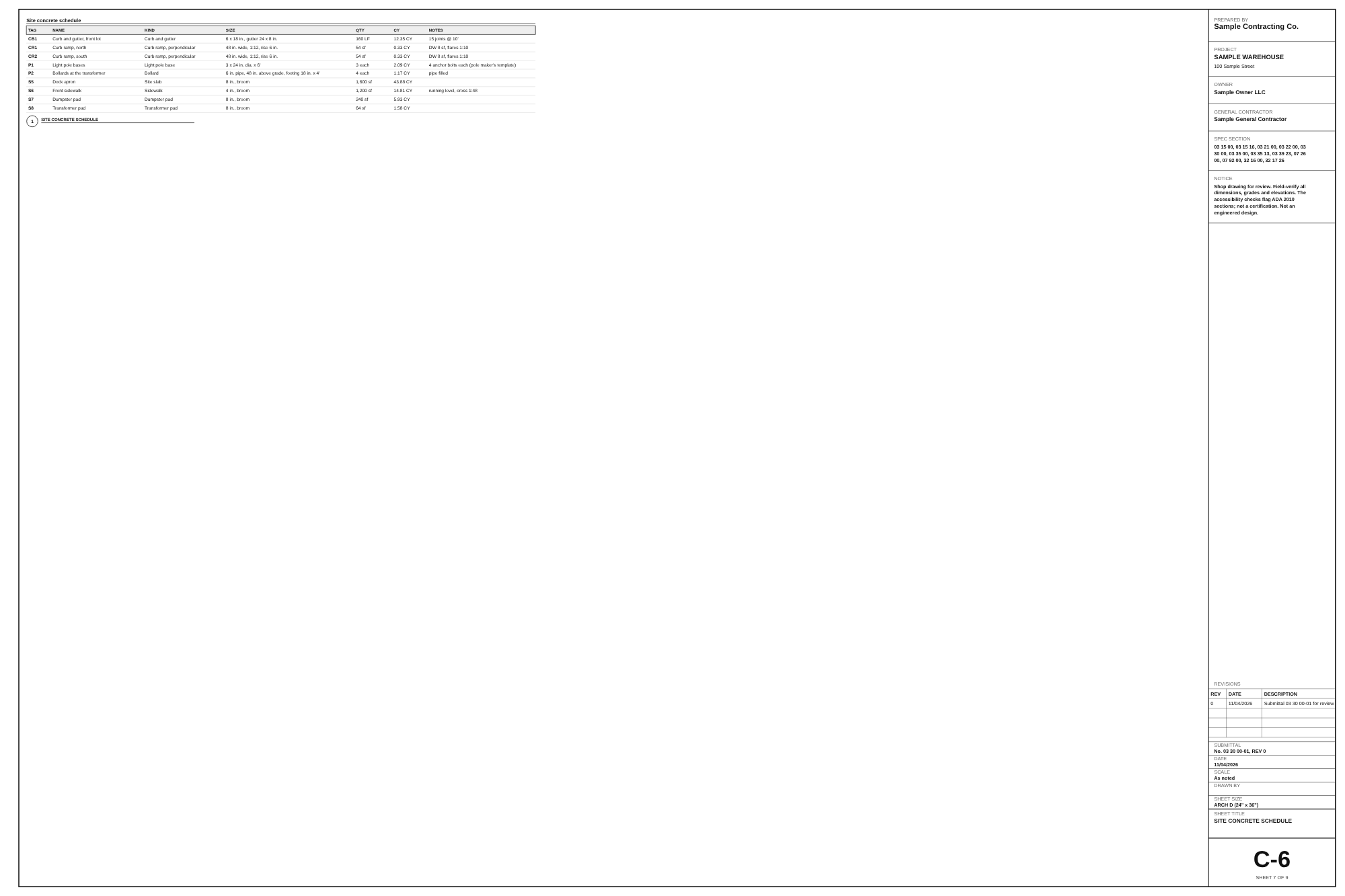
The site concrete schedule: CB1 curb and gutter, 6 x 18 in. with a 24 x 8 in. gutter, 160 LF with joints at 10 ft; CR1 and CR2 perpendicular curb ramps, 48 in. wide at 1:12 for a 6 in. rise, each with 8 sf of detectable warning and 1:10 flares; P1, 3 light pole bases 24 in. across and 6 ft deep with 4 anchor bolts each (to the pole maker's template); P2, 4 bollards of 6 in. pipe filled, 48 in. above grade on 18 in. x 4 ft footings; and the apron, sidewalk and pads.

Field tip: Curb and Curb ramp are tools on the plan, like Slab / walk; each site item has its tag on the site concrete plan.

Step 7: Curb ramp and sidewalk checks in the Concrete Designer

Step 7: Curb ramp and sidewalk checks

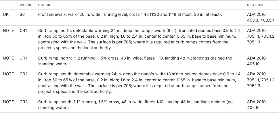
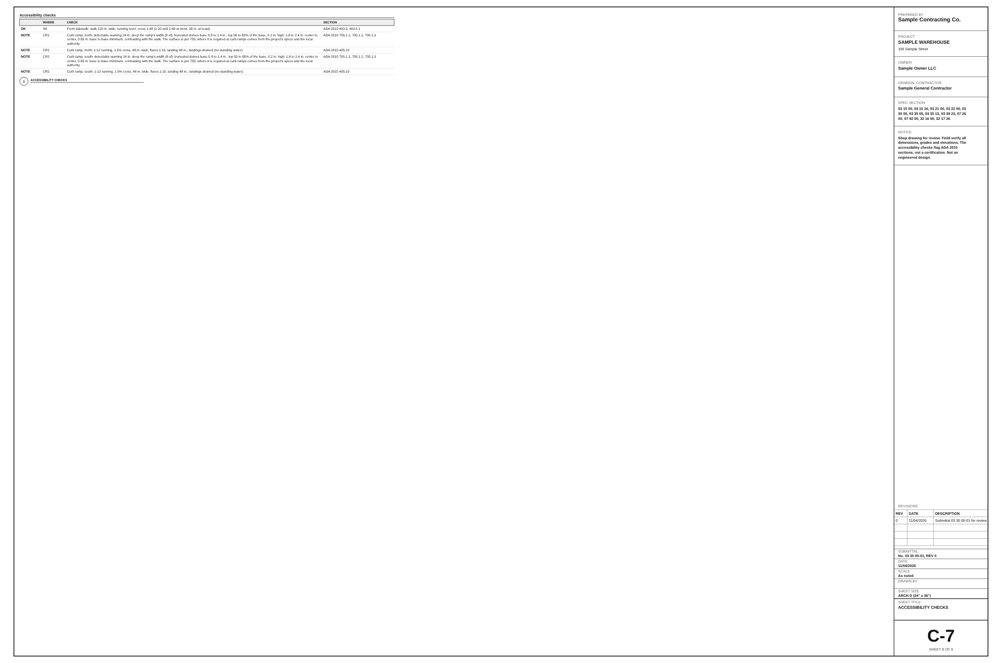
With Accessibility checks on, the Accessibility checks table lists each item with its 2010 ADA Standards section. The front sidewalk passes: 120 in. wide, running level, cross slope 1:48 (403.3, 403.5.1). Each curb ramp is noted with its numbers: 1:12 running, 1.5% cross, 48 in. wide, 1:10 flares, a 48 in. landing, drained (405.10), and its detectable warning 24 in. deep across the ramp's width with the truncated dome sizes (705.1).

Field tip: Checks and flags, not a certification: where detectable warnings are required comes from the project's specs and the local authority.

Step 8: Send to BidRidge in the Concrete Designer

Step 8: Send to BidRidge

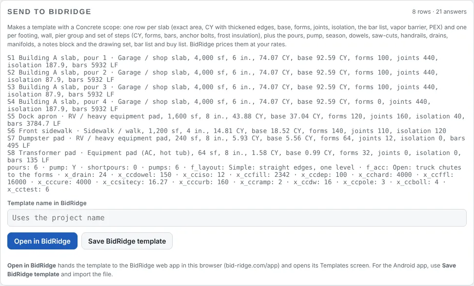
Send to BidRidge: 8 rows · 21 answers. Each slab is a row with its yards, base, forms, joints, isolation and bars; the answers carry the pours and the pump and the commercial lines: 150 construction joint dowels, 2,342 LF of joint filler, the depression edges, 4,000 sf of hardener, 16,000 sf of FF/FL, the wet cure, 16.27 CY of site concrete, 160 LF of curb and gutter, 2 curb ramps with 16 sf of detectable warnings, 3 pole bases, 4 bollards and testing coordination for 6 pours, priced at your rates.

Field tip: Open in BidRidge updates the job when the design was opened from a concrete job, and keeps what you typed there.

Step 9: The Submittal set in the Concrete Designer

Step 9: The Submittal set

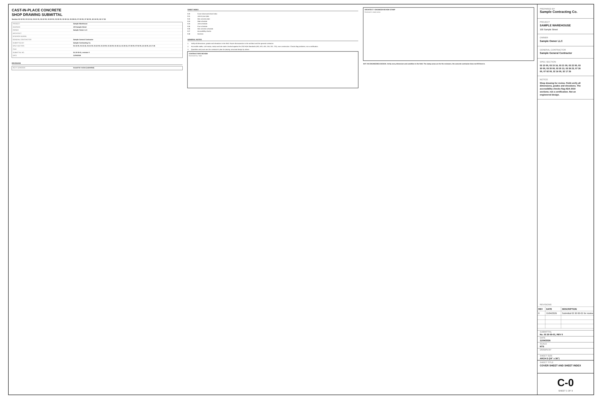
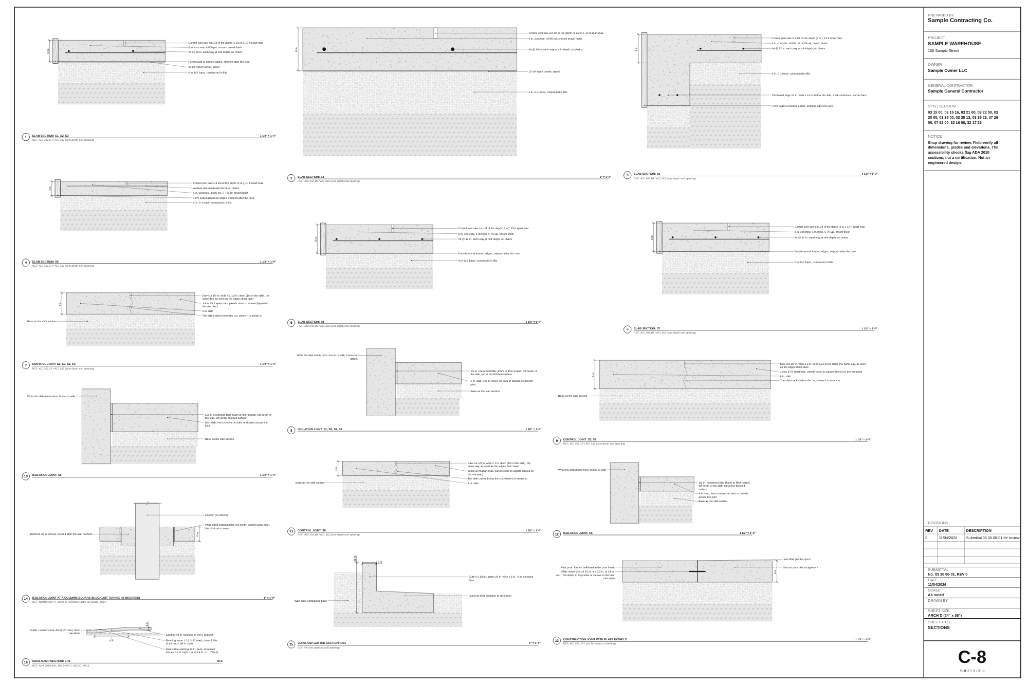
Drawing set, Sheets for: Submittal set. The full set on ARCH D has 9 sheets: C-0 Cover sheet and sheet index, C-1 Joint & pour plan, C-2 Site concrete plan, C-3 Slab schedule, C-4 Joint schedule, C-5 Pour schedule, C-6 Site concrete schedule, C-7 Accessibility checks, C-8 Sections. The 11x17 shop set has 11: the typical details first, then the plans and schedules. The drawing set (install) keeps the commercial pages after the site plan, rebar, sections and pour pages: the joint & pour plan, site concrete plan, the schedules, the accessibility checks, the commercial sections and the notes.

Field tip: The Submittal set is download only: Save PDF. It is never added to the BidRidge job.

What you get

The drawing set, the lists and the files

Real files from this sample, made by the designer. Tap a page to see it full size. Yours carry your company, the client and the address.

C-0 Cover sheet and sheet index
C-1 Joint & pour plan
C-2 Site concrete plan
C-3 Slab schedule
C-3 Slab schedule
C-4 Joint schedule
C-4 Joint schedule
C-5 Pour schedule
C-5 Pour schedule
C-6 Site concrete schedule
C-7 Accessibility checks
C-8 Sections
C-8 Sections
Submittal (11x17 shop) C-1 Typical details

More in the guide

Try it on your own job

Open the sample, change it to your measurements, and send it to a BidRidge quote. Drawing is free; the drawing set, the lists and the quote come with a BidRidge license or the 14-day trial.

In the Concrete Designer, tap Open project and pick the sample file: it opens as the warehouse slab and site in this chapter.

Sample designs: names, sizes and clients are made up. Prices are BidRidge's starting rates; set your own. The designers check against common guidelines (IRC, NKBA and the makers' published numbers) to help you catch mistakes. They don't replace your building department or the manufacturer's installation instructions: verify with them.