1Step 1: Start a blank Commercial design
A clad wall is a partial-height wall clad on both faces, like the knee wall at a nurse station. Tap New design, pick Commercial, and Start blank.

Chapter 24 · Cabinet DesignerBeta
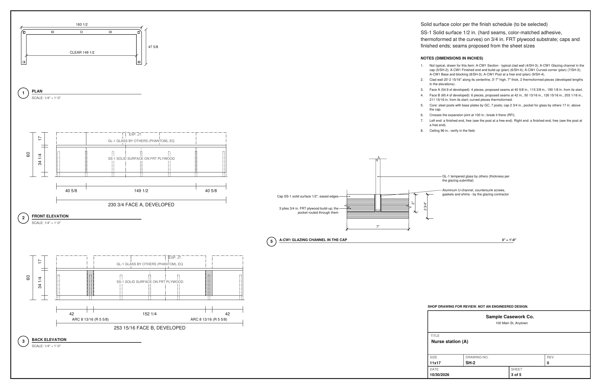
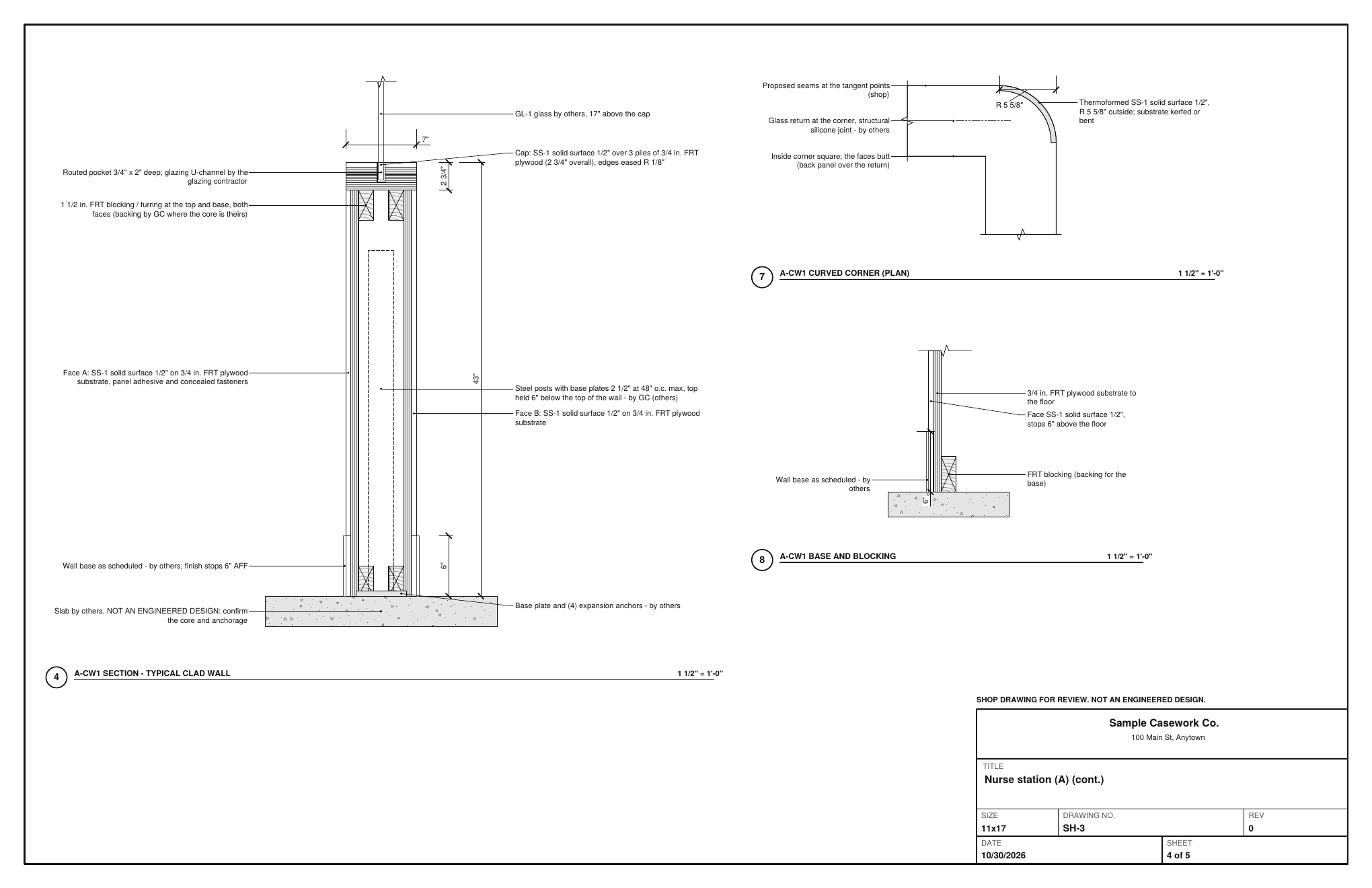
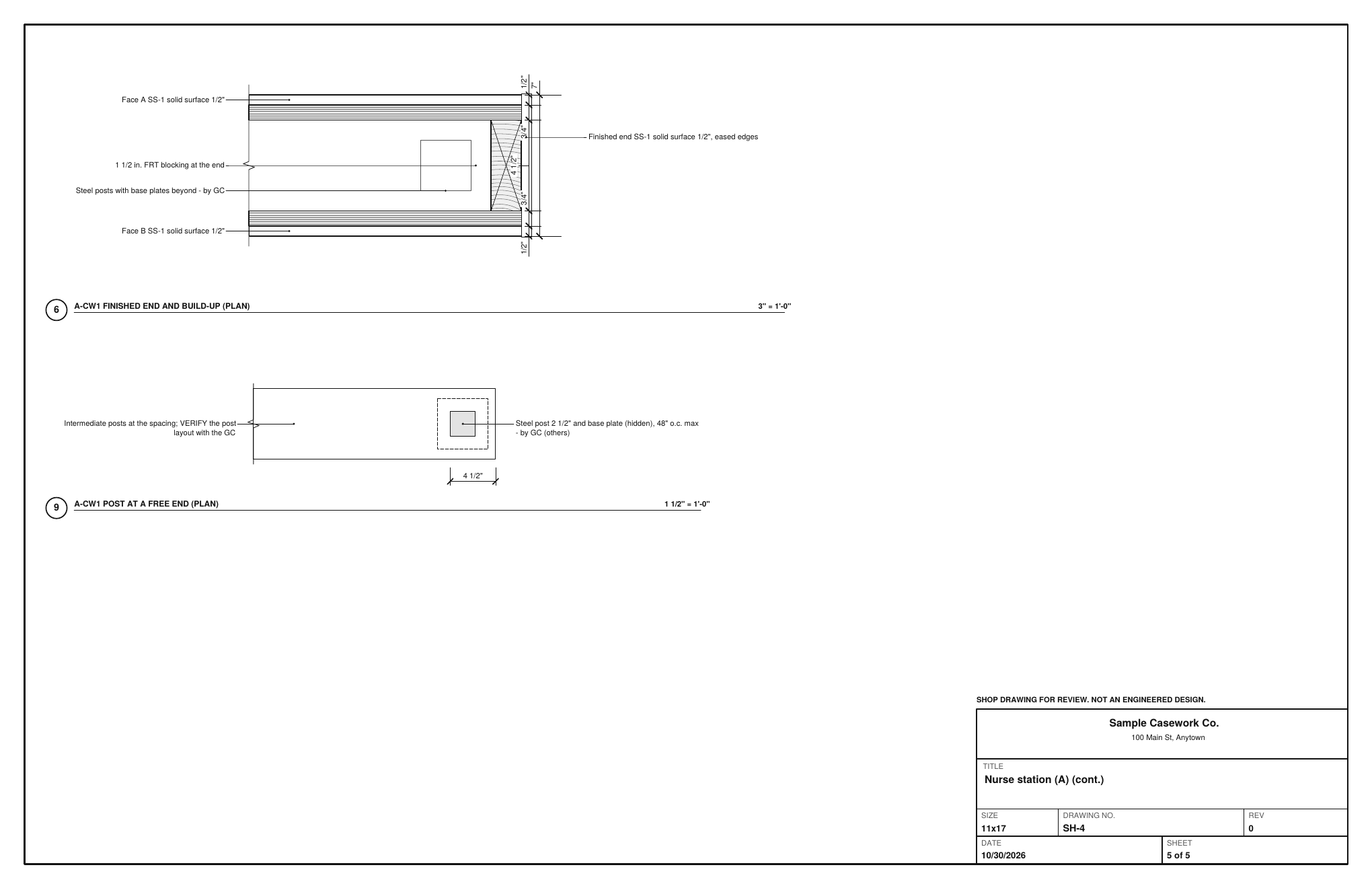
A partial-height wall clad on both faces, like the knee wall at a nurse station: we type its plan path, pick the faces, the core of steel posts and the cap with a glazing pocket, read the developed elevation, the plan and the checks, find the thermoformed corners in the cut list, and print the Submittal set on 11x17 shop sheets.
In the designer, tap Open project and pick the sample file. It opens exactly as in the video.
A clad wall is a partial-height wall clad on both faces, like the knee wall at a nurse station. Tap New design, pick Commercial, and Start blank.
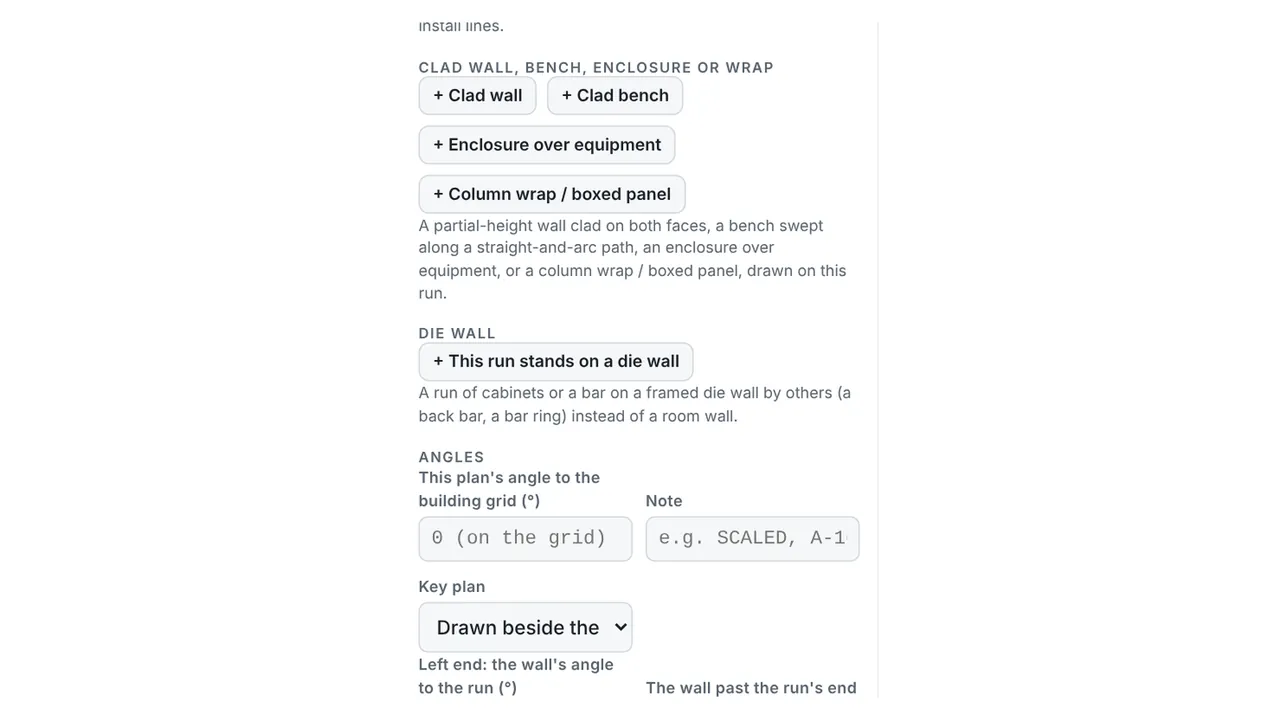
Name the run Nurse station. Further down the Wall card, under Clad wall, bench, enclosure or wrap, tap Clad wall.
Field tip: The same section makes a clad bench, an enclosure over equipment or a column wrap.
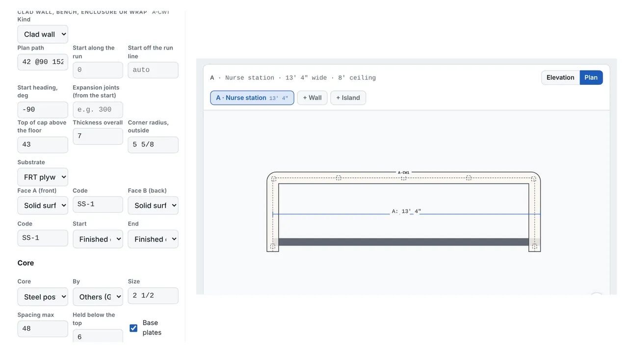
A number is a straight and @90 is a square corner: 42 @90 152.25 @90 42. Set the start heading (-90) and a 5 5/8″ outside corner radius, then tap Fit the run to it.
Field tip: R<radius>@<degrees> makes an arc instead of a square corner (chapter 25).
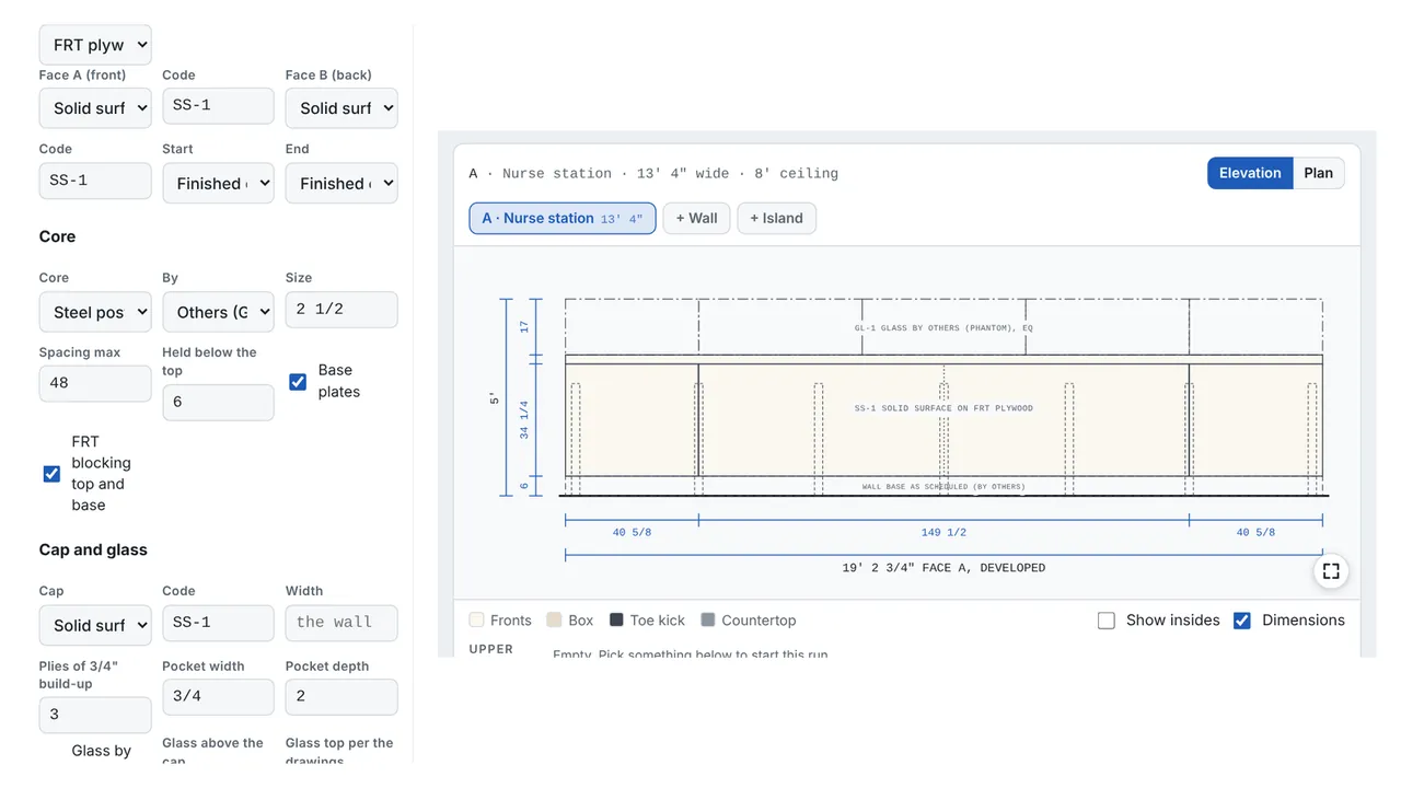
Each face gets a finish: solid surface, laminate, veneer or by others; here SS-1 solid surface on FRT plywood both sides, with both ends finished. The core is steel posts with base plates, 48″ apart at most and held 6″ below the top: by others here, priced when they're yours.
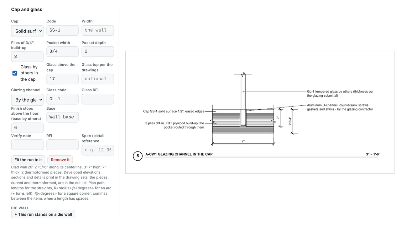
The cap is three plies of build-up under solid surface, with a routed pocket for the glazing channel. Glass by others stands 17″ above it, in equal panels. The finish stops 6″ above the floor, over a base by others.
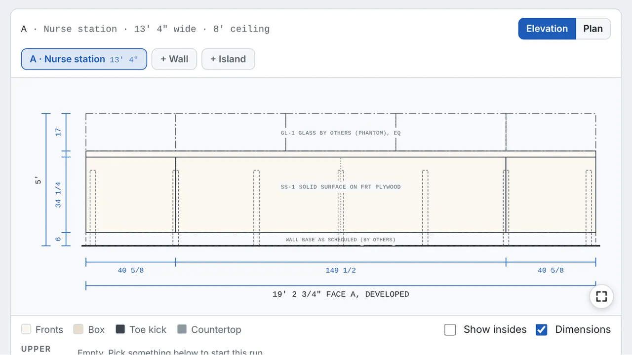
The elevation is developed, unrolled flat: all of face A, the corners between their tangent points, the proposed seams dotted, the posts hidden, and the glass and the base by others in phantom.
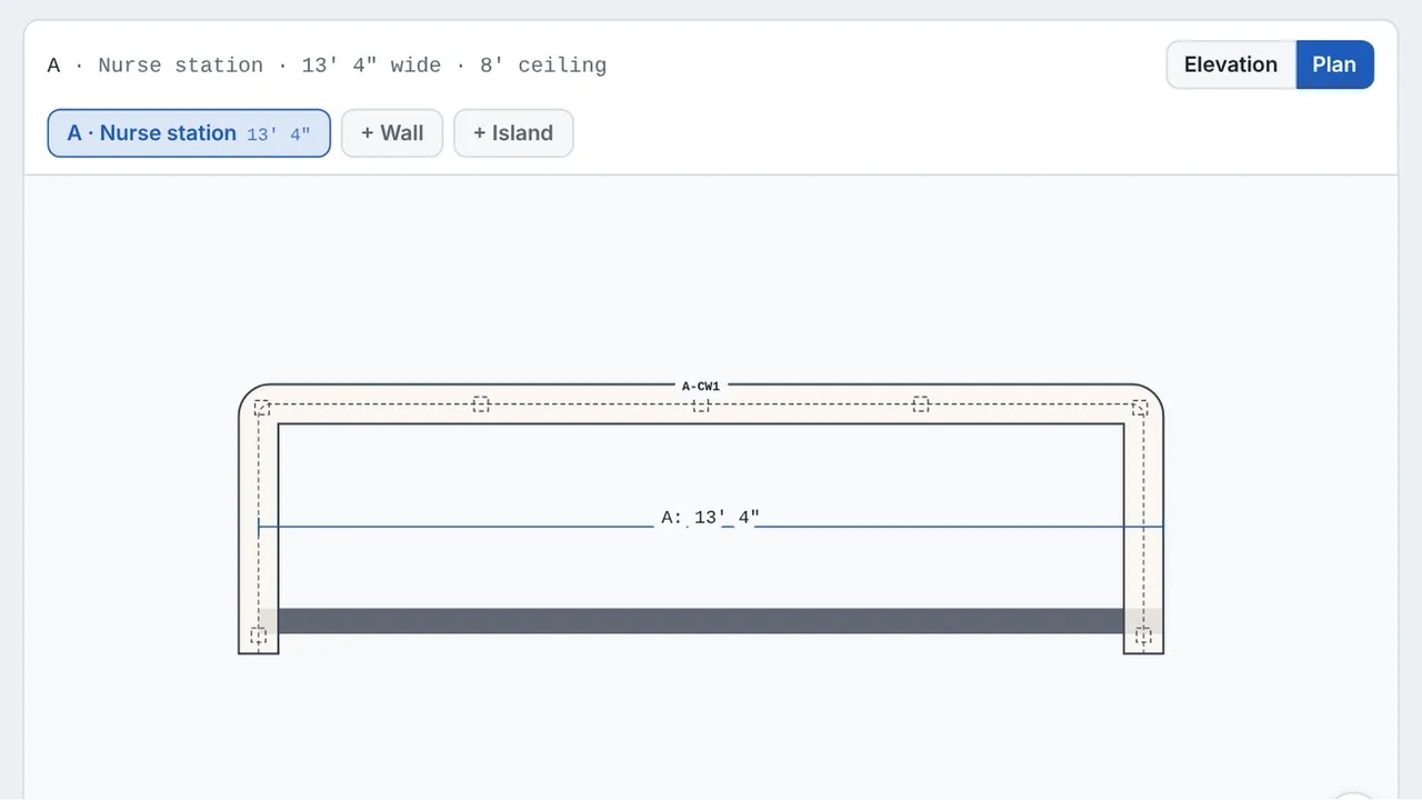
Tap Plan for the outline, the centerline and the posts.
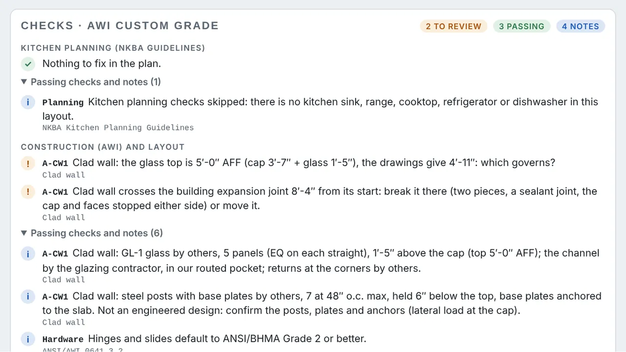
Type the glass top from the drawings (59″) and an expansion joint 100″ from the start. The cap plus the glass comes to 5′-0″, so it asks which governs; the wall crosses the joint, so it says break it there. It also notes this isn't an engineered design: confirm the posts and anchors.
Field tip: These are the sample's two checks to review: answer them before you send the set.
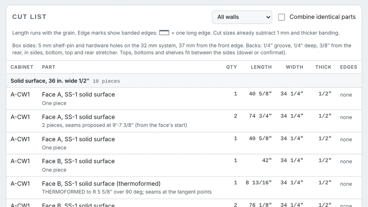
The corner pieces are flagged thermoformed, with their radius, and the long faces are split at the proposed seams.
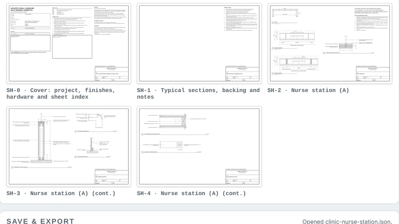
Open the Drawing set. Sheets for: Submittal; Submittal format: Shop sheets, 11×17; then Preview sheets.
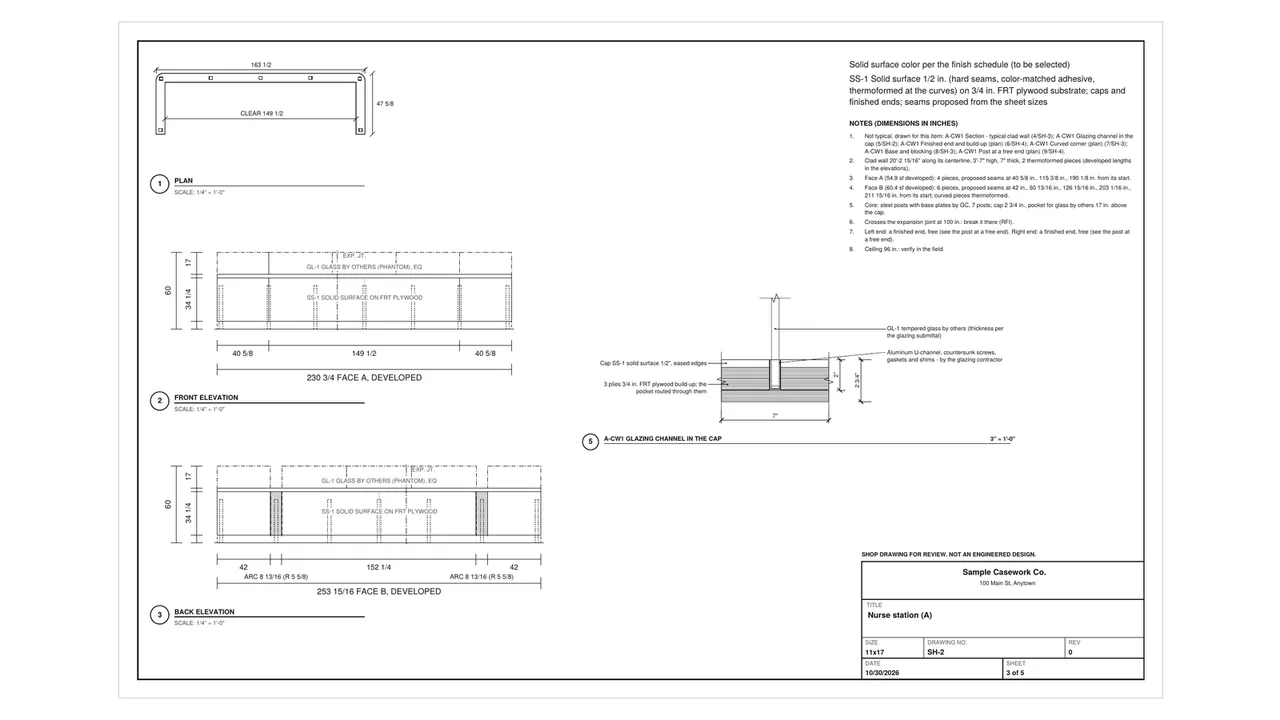
A cover with the project, finishes, hardware and the sheet index, the typical sheet with the notes, then the wall: its plan, both faces developed and the glazing channel in the cap, with the section, the curved corner, the base, the finished end and the posts on two continuation sheets. Save PDF, and send it for review.
Field tip: The submittal is download only: it isn't added to the BidRidge job.
What you get
Real files from this sample, made by the designer. Tap a page to see it full size. Yours carry your company, the client and the address.
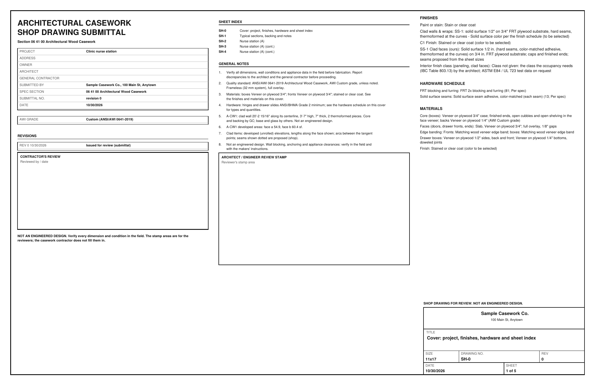
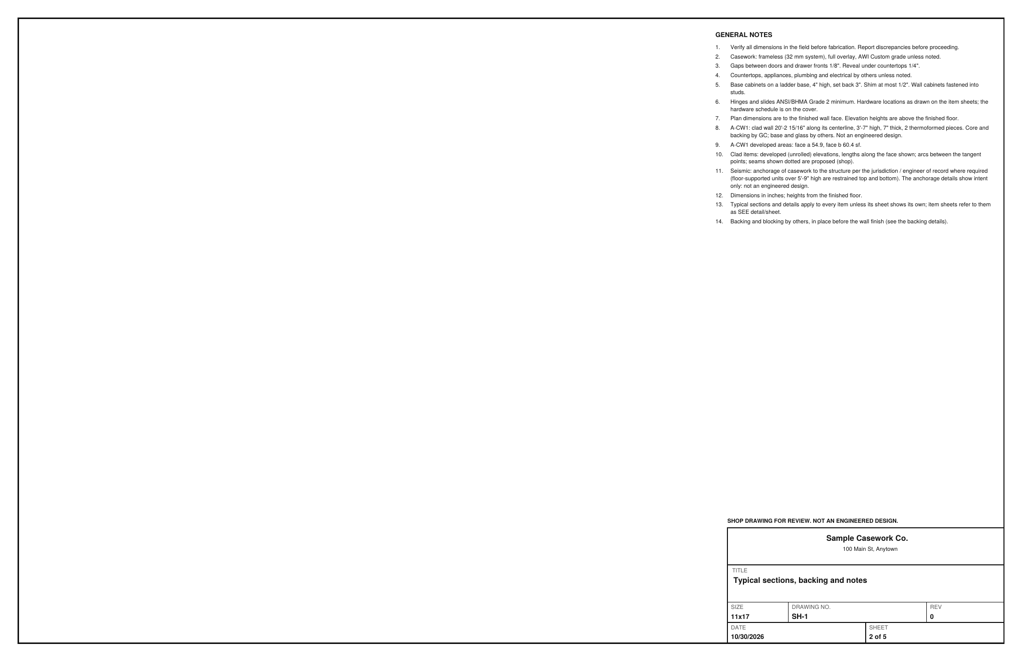
Open the sample, change it to your measurements, and send it to a BidRidge quote. Drawing is free; the drawing set, the lists and the quote come with a BidRidge license or the 14-day trial.
In the designer, tap Open project and pick the sample file. It opens exactly as in the video.
Sample designs: names, sizes and clients are made up. Prices are BidRidge's starting rates; set your own. The designers check against common guidelines (IRC, NKBA and the makers' published numbers) to help you catch mistakes. They don't replace your building department or the manufacturer's installation instructions: verify with them.